

Overview
In this tutorial, we will learn interfacing of 0-25V DC Voltage Sensor with Arduino to measure DC Voltages. Earlier, we made 0-50V DC Voltmeter to measure the output voltages & also learned about the DC−to−DC converters.
The voltage sensor module is a 0-25 DC voltage sensing device that is based on a resistive voltage divider circuit. It reduces the input voltage signal by the factor of 5 and generates a corresponding analog output voltage. This is the reason why you can measure the voltage up to 25V using the 5V analog pin of any microcontroller.
In this project we will first interface the voltage sensor module with Arduino and measure the different Battery voltages. We will then use a small 0.96″ I2C OLED Display to observe the output voltage. This voltage measurement circuit is small & portable and you can use it to detect under or over-voltage faults in electrical circuits.
Bill of Materials
The list of materials required for this project are as follows. You can purchase all the components from Amazon.
| S.N. | Components | Quantity | Purchase Links |
|---|---|---|---|
| 1 | Arduino Nano Board | 1 | Amazon | AliExpress |
| 2 | 0-25V Voltage Sensor Module | 1 | Amazon | AliExpress |
| 3 | 0.96" I2C OLED Display | 1 | Amazon | AliExpress |
| 4 | Jumper Wires | 20 | Amazon | AliExpress |
| 5 | Breadboard | 1 | Amazon | AliExpress |
0-25V Voltage Sensor Module

The Voltage Sensor Module is a simple but very useful module that uses a potential divider to reduce an input voltage by a factor of 5. The 0-25V Voltage Sensor Module allows you to use the analog input of a microcontroller to monitor voltages much higher than it is capable of sensing.
Features & Specifications
1. Output Type: Analog
2. Input Voltage (V): 0 to 25
3. Voltage Detection Range (V): 0.02445 to 25
4. Analog Voltage Resolution (V): 0.00489
5. Dimensions: 4 × 3 × 2 cm
Voltage Sensor Module Pinout
The voltage sensor module has 5 pins, 2 on the front side and 3 on the backside.
- VCC: Positive terminal of the External voltage source (0-25V)
- GND: Negative terminal of the External voltage source
- S: Analog pin connected to Analog pin of the microcontroller
- +: Not Connected
- -: Ground Pin connected to GND of microcontroller
Voltage Sensor Module Design & Construction
The Voltage Sensor is basically a Voltage Divider consisting of two resistors with resistances of 30KΩ and 7.5KΩ i.e. a 5 to 1 voltage divider. Hence the output voltage is reduced by a factor of 5 for any input voltage . The internal circuit diagram of the Voltage Sensor Module is given below.

The Arduino analog input pin accepts voltages up to 5V. Hence you can use this module easily with Arduino. If the controller has 3.3V systems, the input voltage should not be greater than 3.3Vx5=16.5V.
Arduino AVR chips have 10-bit AD, so this module simulates a resolution of 0.00489V (5V/1023), so the minimum voltage of the input voltage detection module is 0.00489Vx5=0.02445V.
Interfacing 0-25V DC Voltage Sensor Module with Arduino
Let us learn interfacing of Voltage Sensor Module with Arduino. The circuit diagram is given below.

The connection is very simple. Connect the Signal (S) and Negative (-) pin of Voltage Sensor to Arduino A0 & GND pin respectively.
Source Code/Program
|
1 2 3 4 5 6 7 8 9 10 11 12 13 14 15 16 17 18 19 20 21 22 23 24 25 26 27 28 29 30 31 32 33 34 35 36 37 38 39 40 41 |
// Define analog input #define ANALOG_IN_PIN A0 // Floats for ADC voltage & Input voltage float adc_voltage = 0.0; float in_voltage = 0.0; // Floats for resistor values in divider (in ohms) float R1 = 30000.0; float R2 = 7500.0; // Float for Reference Voltage float ref_voltage = 5.0; // Integer for ADC value int adc_value = 0; void setup() { // Setup Serial Monitor Serial.begin(9600); Serial.println("DC Voltage Test"); } void loop(){ // Read the Analog Input adc_value = analogRead(ANALOG_IN_PIN); // Determine voltage at ADC input adc_voltage = (adc_value * ref_voltage) / 1024.0; // Calculate voltage at divider input in_voltage = adc_voltage / (R2/(R1+R2)) ; // Print results to Serial Monitor to 2 decimal places Serial.print("Input Voltage = "); Serial.println(in_voltage, 2); // Short delay delay(500); } |
To test the working of the sensor, I used 3 different types of batteries and observed the voltage on the Serial Monitor.
Initially the sensor was tested with a 3.7V common Lithium-Ion Battery.

The Serial Monitor showed the correct reading as per the voltage of the Battery.

Similarly testing the sensor with 9V Battery also worked fined.


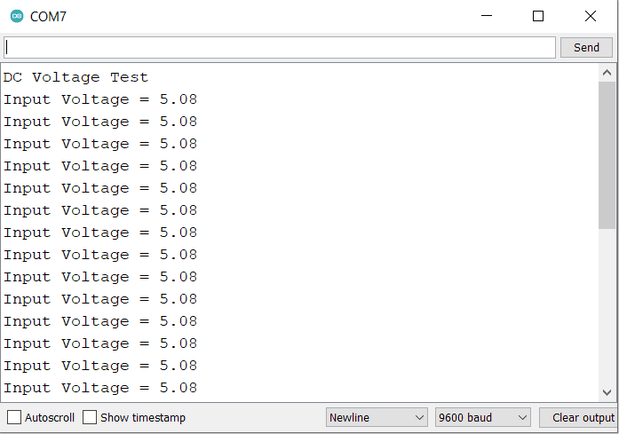
The voltage sensor detected the reading around 5V when tested with Discharged 3S Lithium-Ion Battery.

Making Portable Voltage Detector with OLED Display
Now let us make a portable DC Voltmeter that can measure the voltage from 0V to 25V. Earlier we made 0-50V DC Voltmeter with 7 segment LED Display. But now we will use 0.96″ OLED Display.
The following is the connection diagram for Interfacing Voltage Sensor Module & OLED Display with Arduino Board.

The connection is fairly simple. The voltage sensor module has the connection with Arduino same as earlier. But OLED Display requires 4 connections. Connect the VCC & GND Pin of OLED to Arduino 3.3V & GND pin. Similarly connect the SDA & SCL Pin of OLED to Arduino SDA & SCL Pin, i.e A4 & A5.

Source Code/Program
The code requires two libraries for OLED Display. Donwload the libraries from the following link and add it to the Library Folder of the Arduino.
1. Adafruit GFX Library: https://github.com/adafruit/Adafruit-GFX-Library
2. Adafruit SSD1306 Library: https://github.com/adafruit/Adafruit_SSD1306
|
1 2 3 4 5 6 7 8 9 10 11 12 13 14 15 16 17 18 19 20 21 22 23 24 25 26 27 28 29 30 31 32 33 34 35 36 37 38 39 40 41 42 43 44 45 46 47 48 49 50 51 52 53 54 55 56 57 58 59 60 61 62 63 64 65 66 67 68 69 70 71 |
#include <SPI.h> #include <Wire.h> #include <Adafruit_GFX.h> #include <Adafruit_SSD1306.h> #define SCREEN_WIDTH 128 // OLED display width, in pixels #define SCREEN_HEIGHT 64 // OLED display height, in pixels #define OLED_RESET 4 // Reset pin # (or -1 if sharing Arduino reset pin) #define SCREEN_ADDRESS 0x3C ///< See datasheet for Address; 0x3D for 128x64, 0x3C for 128x32 Adafruit_SSD1306 display(SCREEN_WIDTH, SCREEN_HEIGHT, &Wire, OLED_RESET); // Define analog input #define ANALOG_IN_PIN A0 // Floats for ADC voltage & Input voltage float adc_voltage = 0.0; float in_voltage = 0.0; // Floats for resistor values in divider (in ohms) float R1 = 30000.0; float R2 = 7500.0; // Float for Reference Voltage float ref_voltage = 5.0; // Integer for ADC value int adc_value = 0; void setup() { // Setup Serial Monitor Serial.begin(9600); Serial.println("DC Voltage Test"); if (!display.begin(SSD1306_SWITCHCAPVCC, SCREEN_ADDRESS)) { Serial.println(F("SSD1306 allocation failed")); for (;;); // Don't proceed, loop forever } display.clearDisplay(); } void loop() { // Read the Analog Input adc_value = analogRead(ANALOG_IN_PIN); // Determine voltage at ADC input adc_voltage = (adc_value * ref_voltage) / 1024.0; // Calculate voltage at divider input in_voltage = adc_voltage / (R2 / (R1 + R2)) ; // Print results to Serial Monitor to 2 decimal places Serial.print("Input Voltage = "); Serial.println(in_voltage, 2); display.setCursor(20, 10); //oled display display.setTextSize(1); display.setTextColor(WHITE); display.println("Battery Voltage"); display.setCursor(25, 30); //oled display display.setTextSize(2); display.setTextColor(WHITE); display.print(in_voltage, 2); display.println(" V"); display.display(); delay(500); display.clearDisplay(); } |
When no Voltage source is connected to the input terminal of voltage, the OLED will display 0V output.

Similarly connecting the voltage sensor to 3 different voltage sources gives 3 different results as shown in the image below.


So this is how you can use 0-25V DC Voltage Sensor with Arduino & make your own DC Voltmeter.
Conclusion
In conclusion, the project successfully demonstrated how to interface a 0-25V DC voltage sensor module with an Arduino to measure various battery voltages. The utility of the resistive voltage divider circuit, in reducing input voltage signal by a factor of 5, was underscored. This mechanism enables accurate measurements up to 25V using a 5V analog pin.
The inclusion of a compact 0.96″ I2C OLED display for output voltage visualization enhanced usability. The circuit’s small size and portability, coupled with its ability to detect voltage faults, affirms its value in maintaining electrical circuit efficiency and safety.

")


1 Comment
can we use this voltage sensor for inverter battery capacity? lithium battery pack of 0-30v range ?