
 Monitor using Arduino & Pulse Sensor")
Overview
In this project, we will interface Pulse Sensor with Arduino to Measure Pulse Rate (BPM) or Heart Beat value. The Pulse rate will be displayed on 16×2 LCD Display.
A pulse sensor is a hardware device that can be used to measure heart rate in real-time. When paired with an Arduino microcontroller, you can create a simple yet effective heart rate monitor. This sensor is quite easy to use and operate. Place your finger on top of the sensor and it will sense the heartbeat by measuring the change in light from the expansion of capillary blood vessels.
Components/Hardware Required
We need following components for this project. All the components can be purchased from the given links.
| S.N. | Components | Quantity | Purchase Link |
|---|---|---|---|
| 1 | Arduino UNO Board | 1 | Amazon | AliExpress | SunFounder |
| 2 | Pulse Sensor | 1 | Amazon | AliExpress | SunFounder |
| 3 | 16X2 I2C LCD Display | 1 | Amazon | AliExpress | SunFounder |
| 4 | Jumper Wires | 10 | Amazon | AliExpress | SunFounder |
| 5 | Breadboard | 1 | Amazon | AliExpress | SunFounder |
Pulse Sensor
The Pulse Sensor is a plug-and-play heart-rate sensor for Arduino. It can be used by students, artists, athletes, makers, and game & mobile developers who want to easily incorporate live heart-rate data into their projects.

The essence is an integrated optical amplifying circuit and noise eliminating circuit sensor. Clip the Pulse Sensor to your earlobe or fingertip. Then it into your Arduino, you are now ready to read heart rate.

The front of the sensor comes with the heart logo. This is where you place your finger. On the front side, you will see a small round hole, from where the green LED shines. Just below the LED is a small ambient light photosensor APDS9008 which adjust the brightness in different light conditions.
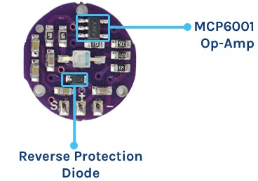
On the back of the module you will find MCP6001 Op-Amp IC, a few resistors, and capacitors. This makes up the R/C filter network. There is also a reverse protection diode to prevent damage if you connect the power leads reverse.
Pulse Sensor Technical Specifications
Physical Characteristics
- Dimensions: Approximately 0.625″ (15.875mm) in diameter
- Weight: Lightweight, usually around a few grams
- Material: Biocompatible materials for safe skin contact
Electrical Characteristics
- Operating Voltage: 3V – 5.5V
- Current Consumption: Typically around 4mA
- Output Signal: Analog (0.3V to VCC)
- Signal Range: 0-1023 (10-bit ADC output of Arduino)
Sensing Technology
- Sensor Type: Photoplethysmogram (PPG)
- Wavelength: Typically around 565nm (Green LED)
Working of the Pulse Sensor
The Pulse Sensor works on the principle of Photoplethysmography (PPG), which is a non-invasive method for measuring changes in blood volume under the skin. The sensor essentially consists of two main components: a light-emitting diode (LED) that shines light into the skin and a photodetector that measures the amount of light that is reflected back. Here’s a detailed explanation of its working:

- Light Emission: A green LED emits light into the skin.
- Reflection & Detection: The light interacts with blood and is partially reflected back, captured by a photodetector.
- Heart Rate: Changes in reflected light create a waveform that correlates with heartbeats.
- Oxygen Level: The amount of reflected light also indicates blood oxygen levels, as oxygenated blood absorbs more green light.
- Signal Filtering: A Low Pass Filter cleans up the noisy, raw signal from the photodetector.
- Amplification: An operational amplifier boosts the filtered signal for better accuracy.
- Data Reading: Finally, an Arduino reads the amplified signal and software algorithms translate it into heart rate and potentially blood oxygen levels.
Pulse Sensor PinOut
The pulse sensor has three pins: VCC, GND & Analog Pin.

Interfacing Pulse Sensor with Arduino
Let us interface the Pulse Sensor with Arduino and start measuring the Pulse Rate/Heart Beat/BPM Value.
Hardware Wiring Diagram
The connection diagram between Pulse Sensor and Arduino is so easy.

- Connect the
REDwire (Power) of the Pulse Sensor to the5Vpin on the Arduino. - Connect the
BLACKwire (Ground) to theGNDpin on the Arduino. - Connect the
PURPLEwire (Signal) toAnalog Pin 0 (A0)on the Arduino.

Using the Jumper Wires you can directly connect the Pulse Sensor with Arduino.
Pulse Sensor Library Installation
Before moving to the coding part, you need to add the Pulse Sensor Library on your Arduino Library Folder.

Download the PulseSensor Playground Library from the Arduino IDE (Go to Sketch -> Include Library -> Manage Libraries, then search for “PulseSensor Playground” and install it).
You visit Pulse Sensor Github repository to see the examples code with different microcontrollers.
Source Code/Program
Now let us take a look at the Pulse Sensor Arduino Code, taken from the library examples.
Open the example sketch that comes with the library (Go to File -> Examples -> PulseSensor Playground -> GettingStartedProject).
|
1 2 3 4 5 6 7 8 9 10 11 12 13 14 15 16 17 18 19 20 21 22 23 24 25 26 27 28 29 30 31 32 33 34 35 36 37 38 39 40 41 42 43 44 45 |
#define USE_ARDUINO_INTERRUPTS true // Include necessary libraries #include <PulseSensorPlayground.h> // Constants const int PULSE_SENSOR_PIN = 0; // Analog PIN where the PulseSensor is connected const int LED_PIN = 13; // On-board LED PIN const int THRESHOLD = 550; // Threshold for detecting a heartbeat // Create PulseSensorPlayground object PulseSensorPlayground pulseSensor; void setup() { // Initialize Serial Monitor Serial.begin(9600); // Configure PulseSensor pulseSensor.analogInput(PULSE_SENSOR_PIN); pulseSensor.blinkOnPulse(LED_PIN); pulseSensor.setThreshold(THRESHOLD); // Check if PulseSensor is initialized if (pulseSensor.begin()) { Serial.println("PulseSensor object created successfully!"); } } void loop() { // Get the current Beats Per Minute (BPM) int currentBPM = pulseSensor.getBeatsPerMinute(); // Check if a heartbeat is detected if (pulseSensor.sawStartOfBeat()) { Serial.println("♥ A HeartBeat Happened!"); Serial.print("BPM: "); Serial.println(currentBPM); } // Add a small delay to reduce CPU usage delay(20); } |
Testing & Results
After uploading the Pulse Sensor Arduino Example code, you can start the testing process.
Place the finger on the Pulse sensor as shown below.

Open the Serial Monitor to see the pulse sensor data.

The Serial Monitor will display the Pulse Rate value whenever it detect the heart beat.
Displaying Pulse Rate (BPM) Value on LCD Display
Instead of displaying the BPM value on Serial Monitor, we can display the value on LCD Display. We can use a 16×2 I2C LCD Display Code and interface with Arduino Board to display Pulse Sensor BPM Value.
Hardware Wiring Diagram
Since we are using an I2C LCD Display, connect it to the Arduino I2C Pins.

- VCC (Power): Connect the VCC pin on the I2C LCD to the 5V pin on the Arduino.
- GND (Ground): Connect the GND pin on the I2C LCD to the GND pin on the Arduino.
- SCL (Clock): Connect the SCL pin on the I2C LCD to the SCL pin (A5) on the Arduino.
- SDA (Data): Connect the SDA pin on the I2C LCD to the SDA (A4) pin on the Arduino.

You may use breadboard or jumper wire for connection.
Source Code/Program
The code requires I2C LCD Library for compilation. Therefore download the library and add it to the Arduino library folder.
Here is a complete code.
|
1 2 3 4 5 6 7 8 9 10 11 12 13 14 15 16 17 18 19 20 21 22 23 24 25 26 27 28 29 30 31 32 33 34 35 36 37 38 39 40 41 42 43 44 45 46 47 48 49 50 51 52 53 54 55 56 57 58 |
// Include necessary libraries #define USE_ARDUINO_INTERRUPTS true #include <PulseSensorPlayground.h> #include <LiquidCrystal_I2C.h> LiquidCrystal_I2C lcd(0x27, 16, 2); // set the LCD address to 0x27 for a 16 chars and 2 line display // Constants const int PULSE_SENSOR_PIN = 0; // Analog PIN where the PulseSensor is connected const int LED_PIN = 13; // On-board LED PIN const int THRESHOLD = 550; // Threshold for detecting a heartbeat // Create PulseSensorPlayground object PulseSensorPlayground pulseSensor; void setup() { // Initialize Serial Monitor Serial.begin(9600); lcd.init(); lcd.backlight(); // Configure PulseSensor pulseSensor.analogInput(PULSE_SENSOR_PIN); pulseSensor.blinkOnPulse(LED_PIN); pulseSensor.setThreshold(THRESHOLD); // Check if PulseSensor is initialized if (pulseSensor.begin()) { Serial.println("PulseSensor object created successfully!"); } } void loop() { lcd.setCursor(0, 0); lcd.print("Heart Rate"); // Get the current Beats Per Minute (BPM) int currentBPM = pulseSensor.getBeatsPerMinute(); // Check if a heartbeat is detected if (pulseSensor.sawStartOfBeat()) { Serial.println("♥ A HeartBeat Happened!"); Serial.print("BPM: "); Serial.println(currentBPM); lcd.clear(); lcd.setCursor(0, 1); lcd.print("BPM: "); lcd.print(currentBPM); } // Add a small delay to reduce CPU usage delay(20); } |
Testing & Results
Upload the above code and you can start testing the sensor working.

Place your finger on Pulse Sensor and you may see the BPM Value displayed on LCD Screen.

After uploading the sketch, the readings may not be immediately accurate. To get reliable results, try to keep your finger as steady as possible while waiting.
Troubleshooting Pulse Sensor Reading
To achieve stable and accurate readings from the Pulse Sensor, consider the following points:
- Check Operating Voltage: Ensure that the sensor is operating within its stable voltage range, which is between 3.3V and 5.5V. Using voltages outside this range can lead to unstable readings.
- Secure the Sensor: If you notice fluctuations in the readings, consider taping the sensor to your finger. This helps maintain constant blood flow, leading to more stable results.
- Be Patient: The sensor may take some time to produce stable output. Patience is key to obtaining reliable readings.
- Avoid External Light: Make sure to minimize exposure to external light sources when taking measurements, as they can interfere with the sensor’s ability to accurately detect pulse.
- Use a Low Pass Filter: If you’re still experiencing noise in the readings, implementing a software-based low pass filter in your code can help smooth out the data.

Conclusion
In this tutorial, we’ve walked you through the step-by-step process of creating a Pulse Rate Monitor using an Arduino and a Pulse Sensor. This project is not only educational but also highly practical, offering a cost-effective solution for monitoring your heart rate in real-time. Whether you’re a healthcare professional, a fitness enthusiast, or simply curious about electronics, this project provides valuable insights into both health monitoring and Arduino programming. We hope you found this guide informative and encourage you to explore further applications of this technology for your personal or professional use.
Here are list of some of the Pulse Sensor Based Projects:
- IoT BPM Monitoring on ThingSpeak
- ECG Display using Pulse Sensor with OLED
- Heart Rate BPM Meter using Easy Pulse Sensor
- IoT Based Patient Health Monitoring System

")


29 Comments
please sir, what could be the reason why my BPM reads progressively ie something like 50, 68, 88,99,114,120,200?
Tightly put ur finger on sensor by wrapping it with sticky wrapper. Moving the finger will change the bpm value.
Same problem occurs with me then how to solve please help me.
Its a wonderful project and is helpful for beginners to learn Arduino with such a phenomenal project.
Why is the library PulseSensorPlayground not being recognized, not turning orange, even there are ccp, h and keyword text file? What’s the problem? Thank you.
Why is the PulseSensorPlayground library not being recognized (not turning orange text) even there are ccp, h and keywords text files? What’s the problem? Thank you.
I think the latest library has been updated. So better google it look some codes in github for latest library.
Is it normal if my value is 229 fixed?
The normal value should be below 100. Actually 70-85 is termed as best value
I followed the tutorial but my sensor gives about 2-3 values and stops after.
What can be the problem?
Do not move your finger. Make the finger stable. Or wrap your finger slightly with wrapper to make the finger immovable. Moving the finger canges the value.
Also these sensors are cheap and can’t give value that we expect.
I followed the tutorial but my sensor stops after 2/3 readings. What can be the problem?
can we see this display on tv connection also
Yes use raspberry pie and observe on monitor.
What is the reason for showing abnormal values that is more than 100?
Hi, can test work on cats pulse rate??
Yes
What should the LCD read when I do not have my finger on it? Seems to sit at 51
Sir I am working on the remote health monitoring project using pulse sensor, temperature (LM35) sensor, Neo 6M GPS module and esp8266 – 01 wifi module with arduino uno. I am using the same above code for pulse sensor without LCD but I am getting values in the range 52 – 220. What could be the problem Sir? is there a need to calibrate it.
Hi, the pulse sensor that I have used here is a highly inaccurate one with a big stability problem. The value will jump from small to very high range. In order to get fixed value do not move your fingers & keep it stable. You can use a capacitor to filter the value as well. If you want better results I highly recommend you to use MAX30100 Pulse Oximeter Sensor.
Hello Sir,
I using the same code as above for interfacing the pulse sensor with arduino uno but i am getting the values in the range 50 – 220. what could be the problem. pls help me. i am working on a project for engineering students
thank u
mostly the output didn’t match to the exact one why?
Can i ask why my lcd display doesn’t show the results like yours? What could the problem be?
how to up load the code please ?
can i get the report along with abstract of the project mentioned above? if it is available , please share me here or to my mail id – [email protected]
How to check its precision and accuracy?
How it follows linearity curve
Nothing happens for me, it prints “We created a pulseSensor Object !” But does not print heart beats at all.
Nevermind the wiring was incorrect
It didn’t prints output on lcd despite all connections are correct.