

Overview
In this project, we will build a Fire Detection System using Flame Sensor & Arduino. Earlier we build a simple Fire Detector Project using Thermistor. But this project uses a specific sensor called Flame Sensor instead of any temperature sensor.
Fire accidents can cause devastating damage to life and property. Early detection of fires is crucial for safety and prevention. With advancements in technology, it’s possible to create a simple yet effective fire detection system using a flame sensor and an Arduino Code.
This post will discuss how to set up a fire detection system that not only senses the presence of a flame but also alerts the surroundings with a visual signal and a melody alarm.
Bill of Materials
For this tutorial I am using the SunFounder Arduino Starter Kit which has 90+ components.
Here are the list of components I am using from this Kit.
| S.N. | Components | Quantity | Purchase Links |
|---|---|---|---|
| 1 | Arduino UNO R4/R3 Board | 1 | Amazon | AliExpress |
| 2 | Flame Sensor | 1 | Amazon | AliExpress | SunFounder |
| 3 | Red LED | 1 | Amazon | AliExpress | SunFounder |
| 4 | Buzzer | 1 | Amazon | AliExpress | SunFounder |
| 5 | Connecting Wires | 10 | Amazon | AliExpress | SunFounder |
| 6 | Type C USB Cable | 1 | Amazon | AliExpress |
| 7 | Breadboard | 1 | Amazon | AliExpress | SunFounder |
Flame Sensor
A flame sensor is a device that can detect the presence of fire or other light sources within a specific wavelength range, typically from 760nm to 1100 nm.

It is an essential component in various applications, especially in safety systems where fire detection is crucial. The Flame Sensor is one such device that utilizes the YG1006 sensor, a high-speed and highly sensitive NPN silicon phototransistor, to detect flames.
Working of the Flame Sensor
IR sensors like all other photosensor work on the principle that a photon of sufficient energy can knock out electrons so that the resistance of the circuit is changed.

An IR sensor consists of an emitter, detector, and associated circuitry. The circuit required to make an IR sensor consists of two parts; the emitter circuit and the receiver circuit.

The emitter is simply an IR LED (Light Emitting Diode) and the detector is simply an IR photodiode that is sensitive to IR light of the same wavelength as that emitted by the IR LED. When IR light falls on the photodiode, its resistance and correspondingly, its output voltage, change in proportion to the magnitude of the IR light received.
Features and Specifications
- Sensor Type: Utilizes YG1006 NPN silicon phototransistor.
- Sensitivity: Specifically sensitive to infrared radiation due to its black epoxy packaging.
- Operating Voltage: Ranges from 3.3V to 5V, making it compatible with most microcontroller platforms.
- Output: Provides both analog and digital outputs for flexibility in interfacing with other circuits.
- Indicator LED: Comes with an LED indicator that lights up when a flame is detected.
- Adjustable Threshold: Features a potentiometer to adjust the detection threshold for different flame intensities.
- Detection Distance: Capable of detecting a lighter flame at a distance of up to 0.8 meters; greater flame intensities can increase this range.
- Detection Angle: Offers a detection angle of approximately 60 degrees, allowing for a focused detection range.
Pinout
The flame sensor module typically has three to four pins:
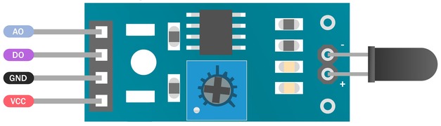
- VCC: Connects to the power supply (3.3V to 5V).
- GND: Connects to the ground of the power supply.
- D0 (Digital Output): Outputs a digital signal (high or low) based on flame detection.
- A0 (Analog Output): Outputs an analog signal proportional to the intensity of the detected flame.
Fire Detection System using Flame Sensor & Arduino
Now let us interface the Flame Sensor with Arduino UNO board and make our own Fire Detection System.
Circuit Diagram & Connections
Here is a simple circuit diagram for this project.

Connect the flame sensor’s VCC to Arduino’s 5V and GND to Arduino’s GND, and its digital output pin to Arduino’s pin 4.

The buzzer’s positive lead connects to Arduino’s pin 3, and its negative lead to another GND pin. Lastly, connect the LED’s anode to Arduino’s pin 2 through a 220-ohm resistor, and its cathode directly to Arduino’s GND.
Source Code/Program
The code for Fire Detection System using Flame Sensor & Arduino is very simple and is written in Arduino IDE. You can copy the following code and paste it on your Arduino IDE editor window.
|
1 2 3 4 5 6 7 8 9 10 11 12 13 14 15 16 17 18 19 20 21 22 23 24 25 26 27 28 29 30 31 32 33 34 35 36 37 38 39 40 41 42 43 44 45 46 |
int flame_sensor_pin = 4; // initializing pin 4 as the sensor output pin int buzzer_pin = 3; // initializing pin 8 as the buzzer pin int led_pin = 2; // initializing the pin 2 as the led pin int flame_pin = HIGH; // state of sensor void setup() { pinMode(led_pin, OUTPUT); // declaring led pin as output pin pinMode(flame_sensor_pin, INPUT); // declaring sensor pin as input pin for Arduino pinMode(buzzer_pin, OUTPUT); // declaring buzzer pin as output pin Serial.begin(9600); // setting baud rate at 9600 } void loop() { flame_pin = digitalRead(flame_sensor_pin); // reading from the sensor if (flame_pin == LOW) // applying condition { Serial.println("FLAME, FLAME, FLAME"); digitalWrite(led_pin, HIGH); // if state is high, then turn high the led playMelody(); // play a melody on the buzzer } else { Serial.println("no flame"); digitalWrite(led_pin, LOW); // otherwise turn it low noTone(buzzer_pin); // stop playing any tone } } void playMelody() { // Play a simple melody: C4, E4, G4, C5 tone(buzzer_pin, 262, 200); // C4 delay(200); tone(buzzer_pin, 330, 200); // E4 delay(200); tone(buzzer_pin, 392, 200); // G4 delay(200); tone(buzzer_pin, 523, 200); // C5 delay(200); } |
From the tools menu, Select the Arduino UNO Board and the Arduino COM port. Then click on the upload icon to upload the code.
Testing & Results
When the flame sensor detects a flame, it sends a digital LOW signal to Digital Pin 4 on the Arduino. The code is written such that when the Arduino detects this LOW signal, it performs two actions.

It sends a HIGH signal to Digital Pin 2, turning on the LED. This serves as a visual indicator that a flame has been detected. It also activates the buzzer on Digital Pin 3 to play a melody.

When the flame sensor does not detect a flame, it sends a HIGH signal to the Arduino, which results in the code sending a LOW signal to the LED pin, turning it off, and stopping any tone on the buzzer.
Video Tutorial & Guide

Conclusion
Creating a fire detection system with an Arduino and a flame sensor is a great project for hobbyists and those looking to understand the basics of electronic sensors and alarms. It demonstrates the potential of simple components and how they can be used to create life-saving systems. With the right setup and programming, anyone can build a basic fire detection system that increases safety and provides a quick response to potential fire outbreaks.

")


1 Comment
Can you send the block diagram of flame detection circuit