

Overview: IoT Water Flow Meter using ESP8266 & Water Flow Sensor
In this project we will learn how to make IoT Based Water Flow Meter using ESP8266 & Water Flow Sensor. We will interface YFS201 Hall Effect Water Flow Sensor with NodeMCU ESP8266 Board. We will display the water flow rate & Total Volume in 0.96″ OLED Display. We will then integrate the hardware with IoT Server. For IoT Server, we will use Thingspeak App. The water flow rate & volume data can be uploaded to Thingspeak Server & can be viewed/monitored from any part of the world.
Water Management System is an important part of City Management. Water management involves supplying water according to the real requirement & without wasting Water. Therefore it is very important to measure water flow rate and volume. Without measuring these parameters, Water Management is almost impossible. Also monitoring the Water Volume, Flow Rate & Water Quality remotely using Internet Connectivity has become very essential. Therefore there is a need for Monitoring Water Management System Online.
There are so many Water Flow Sensors available in the market but are too expensive to use and afford. As a result, a low-cost water flow meter is required. So we will use YFS201 Hall Effect Water Flow Sensor with ESP8266 & design simple IoT Based Water Flow Meter.
Bill of Materials
Following are the components required for making this project. All the components can be easily purchased from Amazon. The component purchase link is given below.
| S.N. | Components Name | Quantity | Purchase Links |
|---|---|---|---|
| 1 | NodeMCU ESP8266 | 1 | Amazon | AliExpress |
| 2 | YF-S201 Hall-Effect Water Flow Sensor | 1 | Amazon | AliExpress |
| 3 | 0.96" I2C OLED Display | 1 | Amazon | AliExpress |
| 4 | Connecting Jumper Wires | 10 | Amazon | AliExpress |
| 5 | Breadboard | 1 | Amazon | AliExpress |
YF-S201 Hall-Effect Water Flow Sensor
 This is an image of the YF-S201 Hall-Effect Water Flow Sensor. This sensor can be connected to the waterline as it has both inlet and outlet. Inside the sensor, there is a pinwheel that measures how much liquid has moved through it. There’s an integrated magnetic hall effect sensor that outputs an electrical pulse with every revolution.
 The sensor comes with three wires:
1. Red (5-24VDC power)
2. Black (ground)
3. Yellow (Hall effect pulse output)
The water flow rate can be calculated by counting the pulses from the output of the sensor. Each pulse is approximately 2.25 milliliters. This Sensor is cheaper and best but not the accurate one as flow rate/volume varies a bit depending on the flow rate, fluid pressure, and sensor orientation. To get better precision of more than 10%, a lot of calibration is required. You can make a basic IoT Based Water Flow Meter using this Sensor.
The pulse signal is a simple square wave so its quite easy to log and convert into liters per minute using the following formula.
|
1 |
Pulse frequency (Hz) / 7.5 = flow rate in L/min |
To learn more about this sensor, you can follow our previous guide here: Arduino & Water Flow Sensor Complete Hookup Guide
IoT Water Flow Meter using ESP8266 & Water Flow Sensor
Now let us interface YF-S201 Hall-Effect Water Flow Sensor with Nodemcu ESP8266 & OLED Display. The OLED Display will show Water Flow Rate & Total Volume of Water passed through the pipe. The same Flow Rate & Volume data can be sent to Thingspeak Server after an interval of 15 seconds regularly. You can switch to Blynk Application if you want immediate data. Similarly using MQTT Protocol better wireless communication can be achieved.
But now let us see the IoT Water Flow Meter Circuit Diagram & Connection.
 Water Flow Sensor is a digital Sensor, so we can connect its output pin to any of the digital pins of ESP8266. In my case, I connected to GPIO2, i.e D4. The sensor works at 5V & can be connected to Vin of ESP8266. Similarly, I2C OLED Display SDA & SCL pins are connected to D2 & D1 of ESP8266 respectively. The OLED Display works at 3.3V so it can be connected to 3.3V pin of Nodemcu.
 I have assembled the circuit on Breadboard. You can use the custom-designed PCB for making the small Water Flow Meter board.
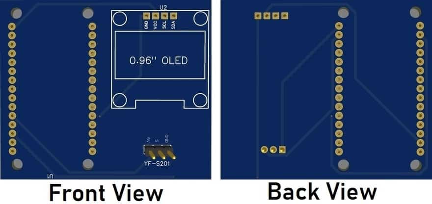
PCB Designing & Ordering Online
The PCB for this project has been designed in EasyEDA online PCB making tool. Below is the front view and Back View of the PCB.
The Gerber File for the PCB is given below. You can simply download the Gerber File and order the PCB from ALLPCB at 1$ only.
You can use this Gerber file to order high quality PCB for this project. To do that visit the ALLPCB official website by clicking here: https://www.allpcb.com/.

You can now upload the Gerber File by choosing the Quote Now option. From these options, you can choose the Material Type, Dimensions, Quantity, Thickness, Solder Mask Color and other required parameters.

After filling all details, select your country and shipping method. Finally you can place the order.
Mathematical Calculation to Measure Flow Rate & Volume
We have determined flow rate by a change in velocity of the water. The water velocity depends on the pressure that forces the through pipelines. The cross-sectional area of the pipe is known and remains constant, thus we calculate the average velocity that indicates the flow rate.
Let us consider Q is the flow rate/total flow of water through the pipe, V is the average velocity & A is the cross-sectional area of the pipe. In such a case the basis relationship for determining the liquid’s flow rate in such cases is Q=VxA
Sensor Frequency (Hz) = 7.5 * Q (Liters/min)
Litres = Q * time elapsed (seconds) / 60 (seconds/minute)
Litres = (Frequency (Pulses/second) / 7.5) * time elapsed (seconds) / 60
Litres = Pulses / (7.5 * 60)
Setting up Thingspeak
Now we need to setup the Thingspeak Account. To set up Thingspeak follow the following Steps:
 Step 1: Visit https://thingspeak.com/ and create your account by filling up the details.
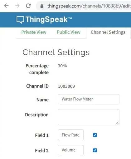
Step 2: Create a New Channel by Clicking on “Channel” & fill up the following details as shown in the image below.
Step 3: Click on API Key, you will see the “Write API Key“. Copy the API Key. This is very important, it will be required in Code Part.

Step 4: You can click on the “Private View” & customize the display window as you want.
So, that’s all from the Thingspeak Setup Part. Now let us move to the programming Part.
Source Code/Program
Now Let us see ESP8266 Water Flow Sensor Code using Arduino IDE. The code can be directly uploaded to the NodeMCU Board. But before that we need few Libraries for OLED Display. So download the Library first and add it to the Arduino IDE.
|
1 2 3 |
String apiKey = "KBD1JSZTUKCXJ15V"; const char *ssid = "Alexahome"; const char *pass = "loranthus"; |
Change the Thingspeak API Key, Wifi SSID & Password from the line above.
The complete source code is given below.
|
1 2 3 4 5 6 7 8 9 10 11 12 13 14 15 16 17 18 19 20 21 22 23 24 25 26 27 28 29 30 31 32 33 34 35 36 37 38 39 40 41 42 43 44 45 46 47 48 49 50 51 52 53 54 55 56 57 58 59 60 61 62 63 64 65 66 67 68 69 70 71 72 73 74 75 76 77 78 79 80 81 82 83 84 85 86 87 88 89 90 91 92 93 94 95 96 97 98 99 100 101 102 103 104 105 106 107 108 109 110 111 112 113 114 115 116 117 118 119 120 121 122 123 124 125 126 127 128 129 130 131 132 133 134 135 136 137 138 139 140 141 142 143 144 145 146 147 148 |
#include <ESP8266WiFi.h> #include <SPI.h> #include <Wire.h> #include <Adafruit_GFX.h> #include <Adafruit_SSD1306.h> #define SCREEN_WIDTH 128 // OLED display width, in pixels #define SCREEN_HEIGHT 64 // OLED display height, in pixels #define OLED_RESET -1 // Reset pin # (or -1 if sharing Arduino reset pin) Adafruit_SSD1306 display(SCREEN_WIDTH, SCREEN_HEIGHT, &Wire, OLED_RESET); String apiKey = "KBD1JSZTUKCXJ15V"; // Enter your Write API key from ThingSpeak const char *ssid = "Alexahome"; // replace with your wifi ssid and wpa2 key const char *pass = "loranthus"; const char* server = "api.thingspeak.com"; #define LED_BUILTIN 16 #define SENSOR 2 long currentMillis = 0; long previousMillis = 0; int interval = 1000; boolean ledState = LOW; float calibrationFactor = 4.5; volatile byte pulseCount; byte pulse1Sec = 0; float flowRate; unsigned long flowMilliLitres; unsigned int totalMilliLitres; float flowLitres; float totalLitres; void IRAM_ATTR pulseCounter() { pulseCount++; } WiFiClient client; void setup() { Serial.begin(115200); display.begin(SSD1306_SWITCHCAPVCC, 0x3C); //initialize with the I2C addr 0x3C (128x64) display.clearDisplay(); delay(10); pinMode(LED_BUILTIN, OUTPUT); pinMode(SENSOR, INPUT_PULLUP); pulseCount = 0; flowRate = 0.0; flowMilliLitres = 0; totalMilliLitres = 0; previousMillis = 0; attachInterrupt(digitalPinToInterrupt(SENSOR), pulseCounter, FALLING); } void loop() { currentMillis = millis(); if (currentMillis - previousMillis > interval) { pulse1Sec = pulseCount; pulseCount = 0; // Because this loop may not complete in exactly 1 second intervals we calculate // the number of milliseconds that have passed since the last execution and use // that to scale the output. We also apply the calibrationFactor to scale the output // based on the number of pulses per second per units of measure (litres/minute in // this case) coming from the sensor. flowRate = ((1000.0 / (millis() - previousMillis)) * pulse1Sec) / calibrationFactor; previousMillis = millis(); // Divide the flow rate in litres/minute by 60 to determine how many litres have // passed through the sensor in this 1 second interval, then multiply by 1000 to // convert to millilitres. flowMilliLitres = (flowRate / 60) * 1000; flowLitres = (flowRate / 60); // Add the millilitres passed in this second to the cumulative total totalMilliLitres += flowMilliLitres; totalLitres += flowLitres; // Print the flow rate for this second in litres / minute Serial.print("Flow rate: "); Serial.print(float(flowRate)); // Print the integer part of the variable Serial.print("L/min"); Serial.print("\t"); // Print tab space display.clearDisplay(); display.setCursor(10,0); //oled display display.setTextSize(1); display.setTextColor(WHITE); display.print("Water Flow Meter"); display.setCursor(0,20); //oled display display.setTextSize(2); display.setTextColor(WHITE); display.print("R:"); display.print(float(flowRate)); display.setCursor(100,28); //oled display display.setTextSize(1); display.print("L/M"); // Print the cumulative total of litres flowed since starting Serial.print("Output Liquid Quantity: "); Serial.print(totalMilliLitres); Serial.print("mL / "); Serial.print(totalLitres); Serial.println("L"); display.setCursor(0,45); //oled display display.setTextSize(2); display.setTextColor(WHITE); display.print("V:"); display.print(totalLitres); display.setCursor(100,53); //oled display display.setTextSize(1); display.print("L"); display.display(); } if (client.connect(server, 80)) // "184.106.153.149" or api.thingspeak.com { String postStr = apiKey; postStr += "&field1="; postStr += String(float(flowRate)); postStr += "&field2="; postStr += String(totalLitres); postStr += "\r\n\r\n"; client.print("POST /update HTTP/1.1\n"); client.print("Host: api.thingspeak.com\n"); client.print("Connection: close\n"); client.print("X-THINGSPEAKAPIKEY: " + apiKey + "\n"); client.print("Content-Type: application/x-www-form-urlencoded\n"); client.print("Content-Length: "); client.print(postStr.length()); client.print("\n\n"); client.print(postStr); } client.stop(); } |
Monitoring Water Flow Rate & Volume
Once the Code is uploaded the OLED Display will strat working and will show the flow rate and volume. Initially the flow rate will be 0 liter/minute(L/M). Also Total Volume shown will be 0 Liter(L).
 Once the motor is turned ON & Water Starts flowing, you can see the OLED Display displaying the Flow Rate (F) & Volume(V).

Now you can monitor the Water Flow Rate & Volume Data on Thingspeak Server as well. You just need to visit the Private View of Thingspeak Dashboard.

Video Tutorial & Complete Guide

 & Live Dashboard")


53 Comments
where is the code?
The Code is already given. Check above
Hello everyone. When i’m trie to upload de code give me error.
Arduino: 1.8.13 (Windows 10), Placa:”Arduino Nano, ATmega328P”
C:\Users\ClickBeauty\Desktop\sketch_aug26b\sketch_aug26b.ino:18:0: warning: “LED_BUILTIN” redefined
#define LED_BUILTIN 16
In file included from C:\Program Files (x86)\Arduino\hardware\arduino\avr\variants\eightanaloginputs/pins_arduino.h:23:0,
c:\program files (x86)\arduino\hardware\arduino\avr\variants\standard\pins_arduino.h:54:0: note: this is the location of the previous definition
#define LED_BUILTIN 13
sketch_aug26b:34:16: error: expected initializer before ‘pulseCounter’
void IRAM_ATTR pulseCounter()
sketch_aug26b:34:16: error: expected initializer before ‘pulseCounter’
void IRAM_ATTR pulseCounter()
C:\Users\ClickBeauty\Desktop\sketch_aug26b\sketch_aug26b.ino: In function ‘void setup()’:
sketch_aug26b:57:50: error: ‘pulseCounter’ was not declared in this scope
attachInterrupt(digitalPinToInterrupt(SENSOR), pulseCounter, FALLING);
C:\Users\ClickBeauty\Desktop\sketch_aug26b\sketch_aug26b.ino:57:50: note: suggested alternative: ‘pulseCount’
attachInterrupt(digitalPinToInterrupt(SENSOR), pulseCounter, FALLING);
exit status 1
expected initializer before ‘pulseCounter’
can any one help me? i’m a beginner on this.
thanks
Excellent article written by the author easily understandable .
project working correctly after uploading the given code and API key.
Very good performance of my flow sensor by blowing into it serial monitor display the values as expected
But my OLED not display anything
Any troubleshooting ?
Check the SDA & SCL connection of OLED with Nodemcu board.
Also check the I2C Address of the OLED Display.
Some oled have different I2C address than 0×3C. Try check by changing the I2C address in Code.
Hello, in void setup, you forgot to include “WiFi.begin(ssid,pass);”…. is it supposed to work as it is or you made an ommission
Yes, you need this under the setup function. Thanks, I will modify the code
Hello, excellent project, I have learned a lot with it. I have a question, I have done exactly the same, but I see that on some occasions the esp8266 freezes (and strange characters start to appear through the serial monitor) and I see that it works again when I disconnect the flow sensor, and being connected to it and it works perfectly. Do you have any idea why this can happen?
Hello, I have tried and it works, thank you @ Mr Alam. Next step is to save water flow and volume data in real time to google sheet, is it programmed from nodemcu or from thingspeak?
You can export the logged data from Thinspeak Dashboard. The data is recorded and saved there which can be exported to excel.
Hi there
Love this tutorial!
Please can you create code for Blynk application.I would like this exact setup but to work with Blynk server. Please!!
Thanks in advance.
Me podrias ayudar, porque la thingspeak no me toma los datos
Not sure what Im doing wrong, I copy and paste the entire code into Arduino IDE and verify. I keep getting this message:
Arduino: 1.8.12 (Windows 10), Board: “NodeMCU 1.0 (ESP-12E Module), 80 MHz, 115200, 4M (3M SPIFFS)”
TST1:34:16: error: expected initializer before ‘pulseCounter’
void IRAM_ATTR pulseCounter()
TST1:34:16: error: expected initializer before ‘pulseCounter’
void IRAM_ATTR pulseCounter()
C:\Users\abc\Documents\Arduino\TST1\TST1.ino: In function ‘void setup()’:
TST1:57:50: error: ‘pulseCounter’ was not declared in this scope
attachInterrupt(digitalPinToInterrupt(SENSOR), pulseCounter, FALLING);
exit status 1
expected initializer before ‘pulseCounter’
Did you find a solution for this? I am also getting this error.
expected initializer before ‘pulseCounter is there solution for this please someone should help thanks
please use #define SENSOR D2 instead of #define SENSOR 2
D2 is GPIO4. So instead of D2 use 4 like:
#define SENSOR 4
The specification of YF-S201 shows Output type is 5V TTL and you connect directly to GPIO2 port which is only 3.3V. Will that cause any problem, error or even destroy the ESP8266 ?
There is an internal voltage divider network in ESP8266. So no issues.
Hi, I am using this code but I can see some times the flowrate goes above 50-55L/min, but how is it possible?
The module itself only supports 1-30L/min floRate only.
yes same error for me also.. can anyone clearup?
Hello what happen on my code??
void IRAM_ATTR pulseCounter()
thanku so much!! it helped me a lot!! but I got the flow rate and volume displayed in my oled but it is not properly displayed in my seriel monitor,something like question marks,boxes and random letters..
and thereby not in my thinkspeak channel as well.. could u PLZ help me with that …
Please check the baudrate for Serial monitor part.
And to solve thingspeak issue add some delay between the different commands for thingspeak.
Thank you for the reply sir!! I have checked the baud rate changed it multiple times and yet no change!! Also its not visible in the thingspeak server as well.just to clarify, api key is the one which connects with the thinkgseak server and there is no mention of channel id in the code right?
hello @Mr Alam I am working with a project related to same topic, could you help me to clarify with my doubts? if yes could you provide me your mail id for communication. Or if u feel uncomfortable to disclose your mail id, please do contact me through – jakshay11992gmail.com.
Perfect processing, functional on first start-up, but data is reset after power off. Advise how to keep data in ESP 32 memory?
Store in the rtc memory or eeprom
I use NODEMCU, not everyone saves data? Did you manage the code?
Hello please when I compile the code it gives me error that client was not declared in this scope if could you help me sir
i done with code and works fine but wifi was not connecting to nodemcu will u please help me
I need a Help, My board is not connecting with WIFI . i tried with other new board too not connecting to WIFI help me out on this issue.
Could post code for MQTT?
Thanks
Hello
Everithing is just working fine but i never was able to connect with thingspeak, the wifi of the board is ok and I already add a delay of 15 seconds. Also to try to resolved this I included tge thingspeak library but even with this changes I not able to connect with thingspeak.
Can you please help me? Thank you for all the projects that and especialy for this one.
Hello. I installed chirpstack lorawan server. I want to send the water measurement to this server. Is there a chance to combine your two projects that I have given the web link below? So we will measure liters of water with nodemcu and flowmeter. Then with lora, we will send it to chirpstack over the 2 channel lora gateway you made with esp32.
Project link: https://how2electronics.com/iot-water-flow-meter-using-esp8266-water-flow-sensor/#Mathematical_Calculation_to_Measure_Flow_Rate_Volume
Project link: https://how2electronics.com/lora-based-soil-moisture-monitoring-on-lora-esp32-webserver/
hello how can i know my wifi ssid and password that am supposed to change it in the code
please help
Hi Sir,
I want output on my own application instead of thingspeak.
Please tell me how I can do this?
Thanks
Hi, your wifi ssid and password probably is going to be on your wifi router. Please check it.
Hi, check your ssid and password. Also, try to restart your router. 🙂 Cheers.
Hi, are you using the same version of the water flow sensor? Probably you need to calibrate your sensor and formulas a bit. Maybe your water sensor is not in the correct position or damaged? Cheers.
hello sir. i like your project. i want to add buzzer for low flow rate or pump not run dry. so plzz send code
thank u very much
hi, could you PLEASE address the issue that multiple people have mentioned above, that the sketch will not compile and this error occurs:
error: expected initializer before ‘pulseCounter’
void IRAM_ATTR pulseCounter()
there is then another error related to this one [ In function ‘void setup()’:
water_flow:82:50: error: ‘pulseCounter’ was not declared in this scope
attachInterrupt(digitalPinToInterrupt(SENSOR), pulseCounter, FALLING); ]
PLEASE help with a solution to this.
thank you
This code is specific to the ESP8266. Simply remove IRAM_ATTR
i guess you need to calibrate sensor
excellent project but one request can I get the source code of the thingspeak App?
Can you please explain this part of the code
if (client.connect(server, 80)) // “184.106.153.149” or api.thingspeak.com
{
String postStr = apiKey;
postStr += “&field1=”;
postStr += String(float(flowRate));
postStr += “&field2=”;
postStr += String(totalLitres);
postStr += “\r\n\r\n”;
you did? I’m very interested!
if you wire this as shown you’ll fry your esp8266. the gpio pins on the esp8266 are NOT 5v tolerant. this circuit will pulse 5v onto the gpio pins and fry the esp8266 chip.
Thank you very much for publishing this project which I’ve completed successfully. I have one small issue and wonder how to fix it. When my ESP8266 loses and regains power or I simply restart the board via the restart button, it doesn’t boot when the Signal pin (S) of the water flow meter is connected. Via the circuitry, it is connected to D4/GPIO2 on the board. I read here https://randomnerdtutorials.com/esp8266-pinout-reference-gpios/ that GPIO2 has to be “pulled high” if the board is to boot (“HIGH at boot … boot fails if pulled LOW”) so I assume that, when MP is connected, GPIO2 is pulled low. Indeed, my own readings with a voltmeter show 0V at the pin when S is connected and around 3V when it is not. The following questions seem to arise:
Which of the other GPIO pins could one use for this project such that the boot problem does not occur? (Note: the PCB design and code would both need to be modified if changing the GPIO pin being used). According to the above web page, boot fails if GPIO0 (D3) and GPIO1 (TX) are pulled LOW so I guess they are not options. It also describes GPIO3 (RX) and GPIO16 (D0) as “HIGH at boot” but doesn’t explicitly say “boot fails if pulled LOW”.
If using GPIO2 (as I am having ordered and received the PCBs using the Gerber files provided with project which are wired to GPIO2!) is there a way to fix this problem? I’m thinking of connecting a 10K resistor between S (GPIO2) and either 3V3 (3.3V DC) or perhaps one of 9 (SD2), 10 (SD3) and 16 (D0) which are apparently high (3.3V DC) at boot. I note that the project already uses GPIO16 for the LED and that the web page says “GPIO6 to GPIO11 are usually connected to the flash chip in ESP8266 boards so … are not recommended for use.” (does this apply here?)
Community comments on questions 1 and 2 would be greatly appreciated.
*Typo – “MP” above should have said “S (Signal)”
Can we use EEPROM in this project
The Vcc is 5 volts. Please check what you get aa output. If it is more than 3.3v you can expect strange behavior.
Also use a stable power supply
Hello
I have display I2C OLED 1.3″ – SH1106, can you me please send code for this diplay.
Tnx