

Introduction
This is a getting started tutorial on Realtek AMB82-Mini IoT AI Camera Arduino Dev. Board which is a very powerful alternative to ESP32-CAM Module
The AMB82-MINI development board uses the Realtek RTL8735BDM SoC, making it ideal for battery-operated devices or equipment that need AI network camera applications. This board ensures both low power consumption and strong IoT security. Additionally, programming and learning AI models with this powerful IoT development kit is quite straightforward and easy.
In this tutorial, we will cover the features and pin descriptions of the board, as well as how to program it using the Arduino IDE. We will provide a beginner’s guide for setting up the Arduino IDE to use this board for a range of AI IoT applications. We will also undertake some practical exercises with this board, like making an LED blink and video streaming over a WebServer. A detail comparison between Realtek AMB82-Mini IoT AI Camera and ESP32-CAM Board is explained as well.
This “Getting Started” tutorial for the Realtek AMB82-Mini is crucial, as we plan to use this module for numerous projects. These projects include streaming live video globally, video recording, security camera usage, face recognition, object detection and identification, Embedded AI Vision Camera, along with other projects based on neural networks.
Bill of Materials
We need the following components for this tutorial. You can purchase the components from given links.
| S.N. | Components | Quantity | Purchase Links |
|---|---|---|---|
| 1 | Realtek AMB82-Mini IoT AI Camera Board | 1 | Seeed Studio |
| 2 | Micro-USB Cable | 1 | Amazon | AliExpress |
| 3 | SD Card (Optional) | 1 | Amazon | AliExpress |
Introducing the Realtek AMB82-Mini IoT AI Camera Board
The Realtek AMB82-Mini IoT AI Camera Board is a development tool designed to streamline the creation of AI network camera applications.

Equipped with the highly integrated Realtek RTL8735BDM SoC, this board facilitates low-power 802.11 a/b/g/n WLAN and BLE solutions. Comprising of an Arm® v8M MCU, DualBand Wi-Fi, Bluetooth BLE5, an audio codec, an ISP, H264/H265 encoder, DDR2 128MB memory, and a neural network intelligent engine, the RTL8735BDM SoC ensures efficient amalgamation of diverse applications and controls.
The AMB82-Mini is optimized for battery-powered appliances, demonstrating swift boot-up time in milliseconds and consuming ultra-low power in mA/uA depending upon the applications. Its embedded security architecture with TrustZone/security mechanism and dual-band Wi-Fi ensures secure, high-quality H264/H265 video streaming with minimal power consumption, making it ideal for IoT applications.
In addition, the AMB82-Mini is compatible with multiple programming platforms such as RTOS, IAR, GCC, and Arduino IDE. It is not just limited to wireless network camera designs; the board’s internal NN engine can support edge AI devices, enabling the development of intelligent equipment and a plethora of AI models, including object detection, audio recognition, and facial recognition. With the AMB82-Mini, developers can explore the limitless potential of IoT and AI technology in their future products.
Key Features & Specifications of Realtek AMB82-Mini
- MCU: 32-bit Arm v8M, up to 500MHz
- NPU: Intelligent Engine @ 0.4 TOPS
- Memory: 768KB ROM, 512KB RAM, 16MB Flash, Supports MCM embedded DDR2/DDR3L memory up to 128MB
- Wi-Fi: 802.11 a/b/g/n, Dualband 2.4GHz/5GHz Wi-Fi & Wi-Fi simple config
- Bluetooth: Bluetooth Low Energy (BLE) 5.1
- Security: Hardware cryptographic engine, Secure boot, Trust-Zone, Wi-Fi WEP, WPA, WPA2, WPA3, WPS
- Audio Codec: ADC/DAC/I2S
- ISP/Video: HDR / 3DNR / WDR ; H264/H265/JPEG video encoder 1080p@30fps +720p@30fps
- Camera module: JXF37 1920×1080 full HD CMOS image sensor with wide view angel FOV 130° optical lens
- Interface: 1 Microphone on Dev Board, 2 Micro USB_B, 1 MicroSD card slot, 2 tact switch button, 3 UART, 2 SPI, 1 I2C, 8 PWM, 2 GDMA, Max. 23 GPIOs
Layout Overview of Realtek AMB82-Mini Board
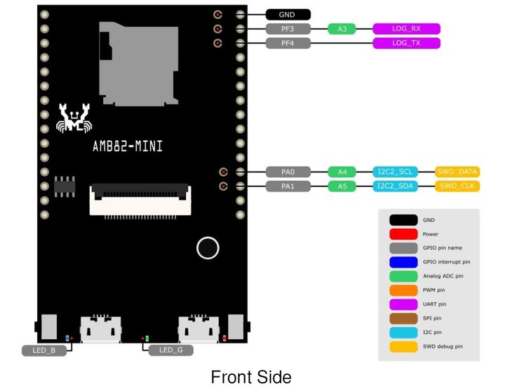
The front side of the board has so many components. It has a SD Card adapter which supports SD card up to 32GB. It can be used for storing images and videos. It has a microphone which supports 3 key features, Audio codec, Video codec and NN (build in NPU for AIoT). The board features internal DDR2 128MB on SoC and 16MB external SPI Nor flash on Dev. Board called W25Q128JVSIQ.

The FPC Connector is used to connect the Camera. It has two push buttons, i.e. Boot Button and Reset Button. The boot button will put the device into programming mode. And reset is used to reset the board while programming or during a normal operation.
There are three LED on the board, i.e. Power LED, LED_B and LED_G. The LED_B is programmable. There are two USB ports as well, i.e. Micro-USB and USB OTG. Using the Micro-USB we can upload the code to the board or establish a serial communication with the computer.
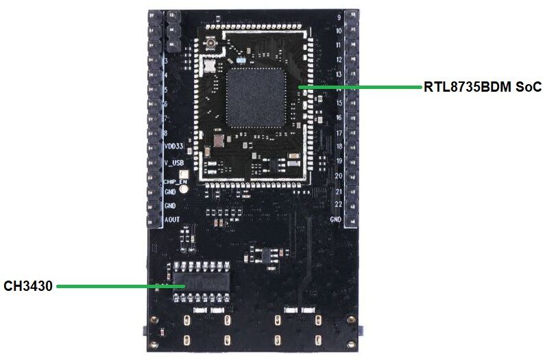
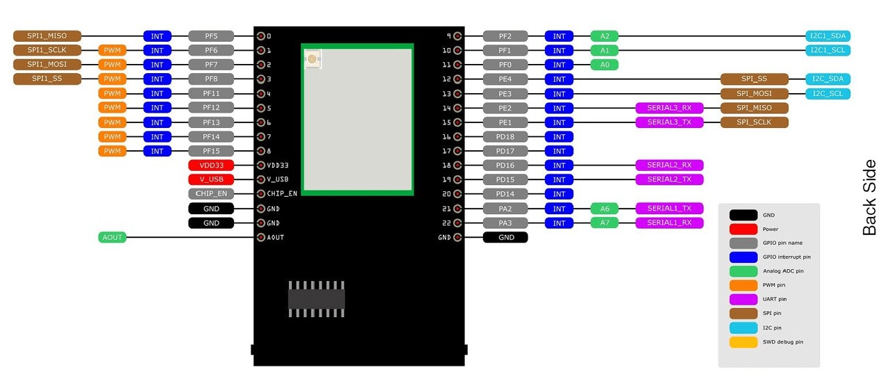
On the backside of the board the main controller Realtek RTL8735BDM SoC is embedded. This chip has ARMv8M architecture and support an amazing speed up to 500 MHz more than twice of ESP32. On the both sides of the board, there are GPIO pins which supports UART, GPIO, ADC, PWM, IIC, SPI, MIPI . Through these interfaces, AMB82 MINI can connect with external electronic components & sensors.
JXF37 Camera Image Sensor Module
The Realtek AMB82-Mini Board has a Camera Module called JXF37. The JXF37 is a 5 Megapixel high-quality camera featuring a Full HD CMOS image sensor with a resolution of 1920×1080 pixels. This impressive resolution provides crystal clear images with fine details, making it ideal for a variety of applications including security, photography, and videography.
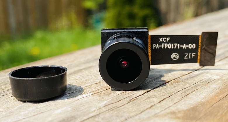
A unique feature of the JXF37 is its wide field of view (FOV) of 130 degrees, provided by its high-quality optical lens. This wide viewing angle allows for a broader perspective, making the camera perfect for capturing expansive landscapes, large group pictures, or wide area surveillance.
ISP Features
- Advanced temporal and spatial noise reduction(3DNR)
- Support major brands of DOL-HDR or Staggered-HDR sensors
- Support MIPI CSI-2 data lane
- Support Auto Banding, Auto Exposure, Auto White Balance
- Black level compensation and dead pixel cancellation
- Lens shading compensation
- Advanced contrast adjustment and sharpness enhancement
- Programmable color matrix and gamma table
- Digital WDR
- Image enhancement(brightness, contrast, saturation, hue and sharpness)
- ISP tuning tool
Pinout of Realtek AMB82-Mini
Important Documents Links
Realtek AMB82-Mini IoT AI Camera Board VS ESP32-CAM Board

Here’s a comparison of the Realtek AMB82-Mini IoT AI Camera Board and the ESP32 CAM Board in a tabular format:
| Specification | AMB82-Mini IoT AI Camera Board | ESP32 CAM Board |
|---|---|---|
| MCU | ARMv8M up to 500MHz | ESP32-D0WDQ6 dual-core 240MHz |
| NPU | Intelligent Engine @ 0.4 TOPS | None |
| Memory | 768KB ROM, 512KB RAM, 16MB Flash, Supports MCM embedded DDR2/DDR3L memory up to 128MB | 520KB SRAM, 4MB Flash |
| Wi-Fi | 802.11 a/b/g/n 1×1, Dualband 2.4GHz/5GHz Wi-Fi | 802.11 b/g/n Wi-Fi |
| Bluetooth | BLE 5.1 | Bluetooth 4.2 |
| Security | Hardware cryptographic engine, Secure boot | None |
| Audio Codec | ADC/DAC/I2S | None |
| ISP/Video | HDR/3DNR/WDR; H264/H265/JPEG video encoder | None |
| Camera Module | JXF37 1920×1080 full HD CMOS image sensor | OV2640 2MP CMOS image sensor 1600 x 1200 |
| Camera Resolution | Maximum 5 Megapixels | 2 Megapixels |
| Programming Platforms | RTOS, IAR, GCC, Arduino IDE | Arduino IDE |
Getting Started with AMB82-Mini using Arduino IDE
The best part the Realtek AMB82-Mini IoT AI Camera Board is it supports Arduino IDE. You can check the Arduino IDE SDK for this board from the GitHub repository.

Before Getting started with Realtek AMB82-Mini Board, connect the Camera and Antenna to the main PCB Board. Also insert the SD Card in SD Card slot.
Setting Up Arduino IDE
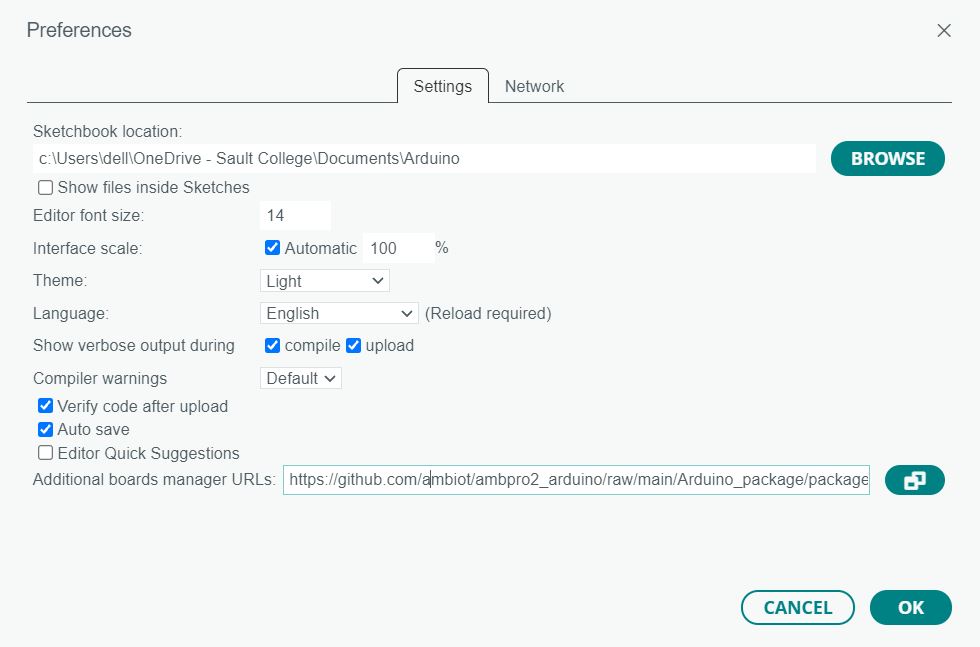
First we need to install the AMB82-Mini Board on Arduino IDE. To do that n your Arduino IDE 2.0, go to File > Preferences.
Copy and paste the following line to the Additional Boards Manager URLs field.
|
1 |
https://github.com/ambiot/ambpro2_arduino/raw/main/Arduino_package/package_realtek.com_amebapro2_index.json |
Open the Boards Manager. You can go to Tools > Board > Boards Manager… or you can simply click the Boards Manager icon in the left-side corner.
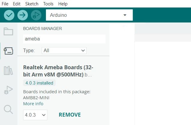
Search for AMEBA and press the install button for Realtek Ameba Boards. That’s it. It should be installed after a few seconds.
Testing the Installation
To test the AMB82-Mini add-on installation, we’ll upload a simple code that blinks the on-board LED.
Copy the following code to your Arduino IDE:
|
1 2 3 4 5 6 7 8 9 10 11 12 13 |
// the setup function runs once when you press reset or power the board void setup() { // initialize digital pin LED_BUILTIN as an output. pinMode(LED_BUILTIN, OUTPUT); } // the loop function runs over and over again forever void loop() { digitalWrite(LED_BUILTIN, HIGH); // turn the LED on (HIGH is the voltage level) delay(1000); // wait for a second digitalWrite(LED_BUILTIN, LOW); // turn the LED off by making the voltage LOW delay(1000); // wait for a second } |
Uploading the Sketch
Connect the AMB82-Mini Board to your computer using the micro-USB cable.

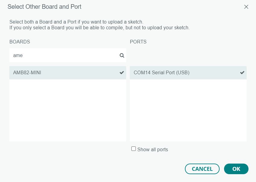
On the top drop-down menu, select the “unknown” board. A new window, as shown below, will open.
You should select your AMB82-Mini Board and the COM port.
The board doesn’t have an automatic programmer. So in order to program the board, follow the following sequence:
- Press and hold the boot button
- Then Press and release the Reset button
- Finally release the boot button
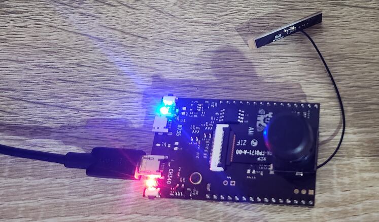
The board has now entered in programming mode. At this moment, the blue LED on the board will turn on, indicating the device is in programming mode.
Now, you just need to click on the Upload button to upload the code.
After uploading the code the Arduino IDE will show following messages.
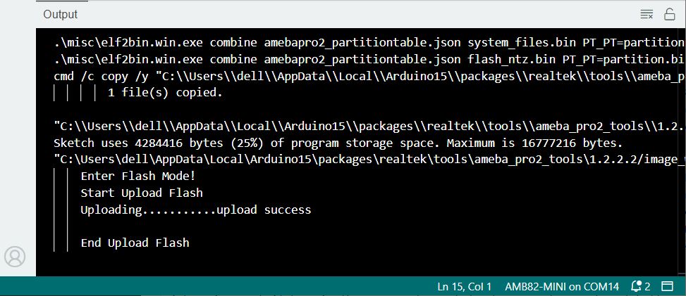
Now press the reset button on the AMB82-Mini Board to run it in Normal Mode. The LED will blink for every 1 second.
This completes the testing part. Now we can start using the board for Artificial Intelligence, Machine Learning, Neural Network applications.
HTTP Video Streaming Example
Now let us test the Camera and stream the Video using WebServer. This example uses the camera to capture a JPEG image repeatedly, and sends the images to a browser continuously using HTTP, creating the effect of a video. We can use Chrome, Firefox or any other Web Borwser to connect to the board’s IP address after it has connected to WiFi, or use the APP V7RC.
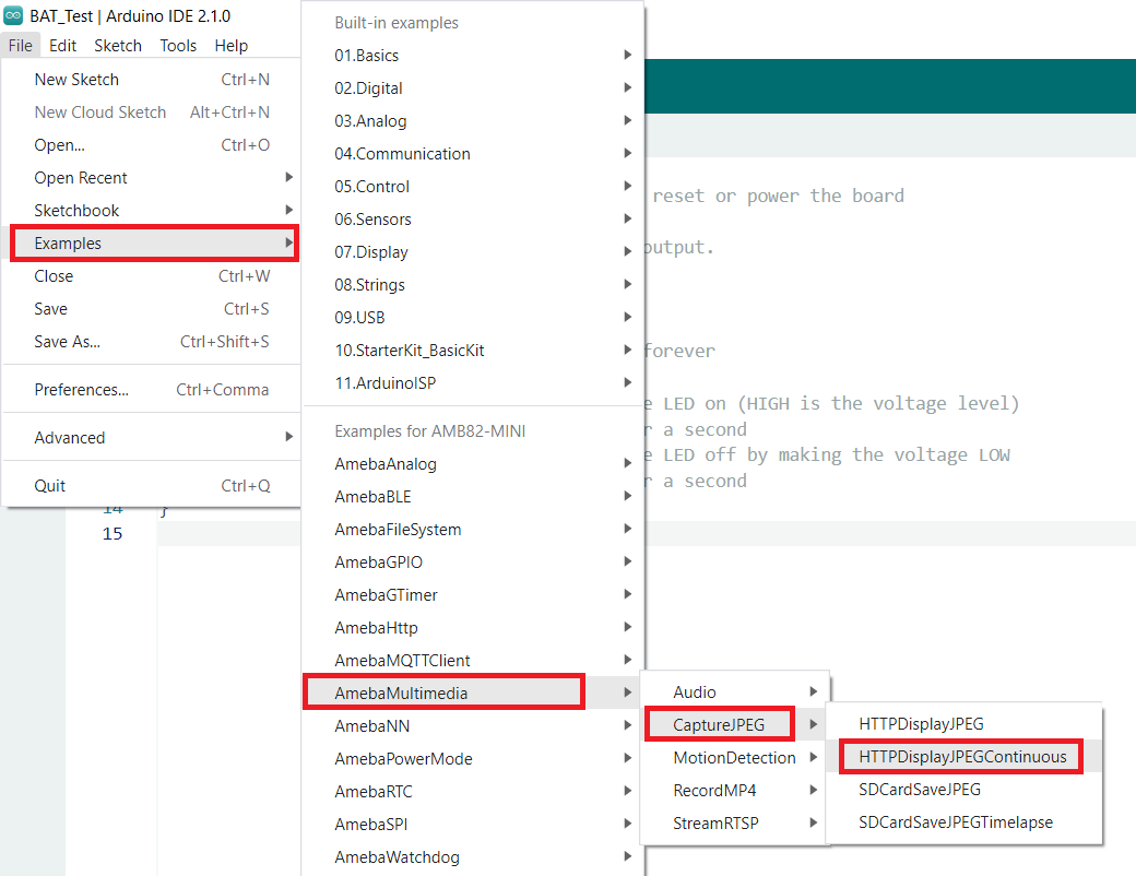
Go to Files > Examples > AmebaMultimedia > CaptureJPEG > HTTPDisplayJPEGContinuous to open the sketch.
Here is the example code.
|
1 2 3 4 5 6 7 8 9 10 11 12 13 14 15 16 17 18 19 20 21 22 23 24 25 26 27 28 29 30 31 32 33 34 35 36 37 38 39 40 41 42 43 44 45 46 47 48 49 50 51 52 53 54 55 56 57 58 59 60 61 62 63 64 65 66 67 68 69 70 71 72 73 74 75 76 77 78 79 80 81 82 83 84 85 86 87 88 89 90 |
#include <WiFi.h> #include "VideoStream.h" #define CHANNEL 0 // Use a pre-defined resolution, or choose to configure your own resolution // Depending on your WiFi network quality, using HD resolution may lead to an inconsistent frame rate //VideoSetting config(VIDEO_HD, CAM_FPS, VIDEO_JPEG, 1); //VideoSetting config(VIDEO_VGA, CAM_FPS, VIDEO_JPEG, 1); VideoSetting config(1024, 576, CAM_FPS, VIDEO_JPEG, 1); char ssid[] = "yourNetwork"; // your network SSID (name) char pass[] = "Password"; // your network password int status = WL_IDLE_STATUS; WiFiServer server(80); uint32_t img_addr = 0; uint32_t img_len = 0; #define PART_BOUNDARY "123456789000000000000987654321" char* STREAM_BOUNDARY = "\r\n--" PART_BOUNDARY "\r\n"; char* IMG_HEADER = "Content-Type: image/jpeg\r\nContent-Length: %lu\r\n\r\n"; void sendHeader(WiFiClient& client) { client.print("HTTP/1.1 200 OK\r\nContent-type: multipart/x-mixed-replace; boundary="); client.println(PART_BOUNDARY); client.print("Transfer-Encoding: chunked\r\n"); client.print("\r\n"); } void sendChunk(WiFiClient& client, uint8_t* buf, uint32_t len) { uint8_t chunk_buf[64] = {0}; uint8_t chunk_len = snprintf((char*)chunk_buf, 64, "%lX\r\n", len); client.write(chunk_buf, chunk_len); client.write(buf, len); client.print("\r\n"); } void setup() { Serial.begin(115200); while (status != WL_CONNECTED) { status = WiFi.begin(ssid, pass); //status = WiFi.apbegin("AmebaVideoAP", "1"); delay(5000); } Camera.configVideoChannel(CHANNEL, config); Camera.videoInit(); Camera.channelBegin(CHANNEL); server.begin(); } void loop() { WiFiClient client = server.available(); if (client) { Serial.println("new client connected"); String currentLine = ""; while (client.connected()) { if (client.available()) { char c = client.read(); Serial.write(c); if (c == '\n') { if (currentLine.length() == 0) { sendHeader(client); while (client.connected()) { Camera.getImage(CHANNEL, &img_addr, &img_len); uint8_t chunk_buf[64] = {0}; uint8_t chunk_len = snprintf((char*)chunk_buf, 64, IMG_HEADER, img_len); sendChunk(client, chunk_buf, chunk_len); sendChunk(client, (uint8_t*)img_addr, img_len); sendChunk(client, (uint8_t*)STREAM_BOUNDARY, strlen(STREAM_BOUNDARY)); delay(5); // Increase this delay for higher resolutions to get a more consistent, but lower frame rate } break; } else { currentLine = ""; } } else if (c != '\r') { currentLine += c; } } } client.stop(); Serial.println("client disonnected"); } else { Serial.println("waiting for client connection"); delay(1000); } } |
Before uploading the code, you need to make some changes to this code. From the lines, change the WiFi SSID and Password.
|
1 2 |
char ssid[] = "yourNetwork"; // your network SSID (name) char pass[] = "Password"; // your network password |
Put the device into programming Mode as we did in LED Blink example above. And the upload the code.
After the code is uploaded successfully, open your Serial Monitor and press the reset button. And look for the messages in Serial Monitor.
The Realtek AMB82-Mini IoT Board will connect to the WiFi Network and print the IP Address of the board.
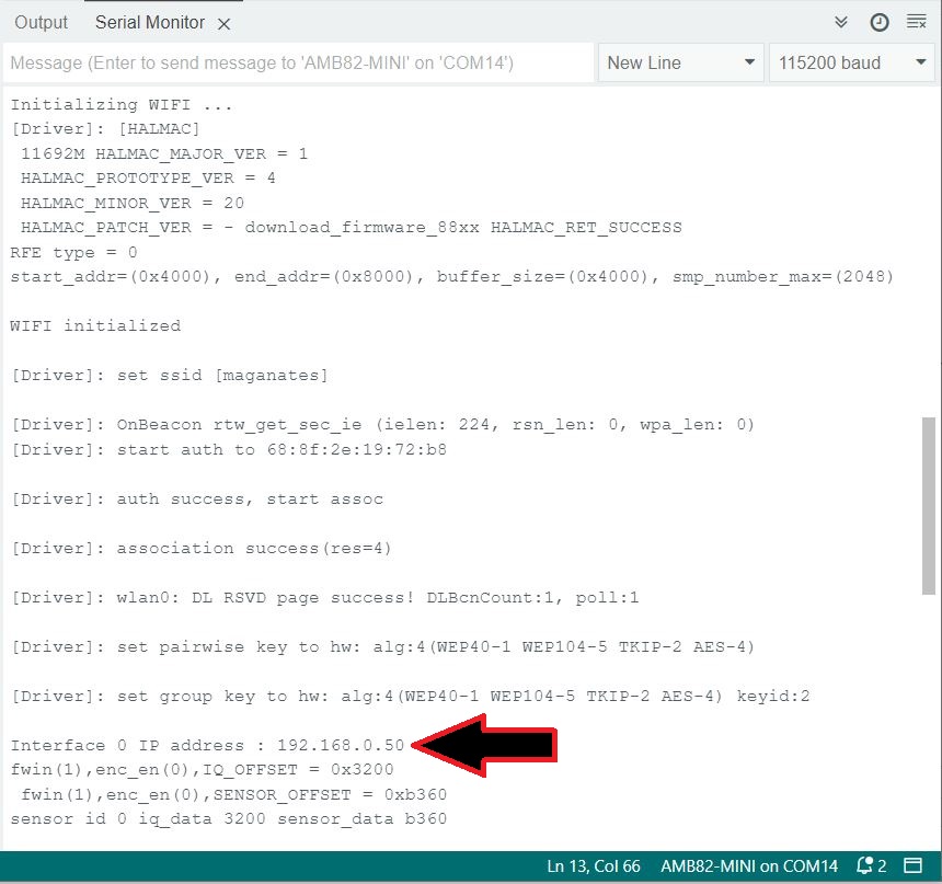
Using this IP Address, we can stream the video. Therefore, copy the IP Address and paste it on your Web Browser Address bar and hit enter.
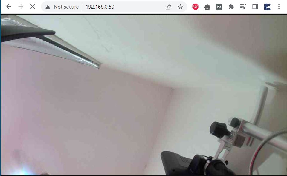
The video stream window will appear here now.
Now you can move the Camera in any direction to check the video streaming in Web Server.

You will observe fast moving video streaming without a lag on your Web Browser.
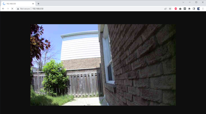
You can move the camera around to see the video stream on the screen. The best thing about this video stream is the resolution is extremely high and moreover the image quality looks so premium and clear.
If you are facing lag in the video or if you have slow internet connection, increase the delay in this following piece of code in loop section.
|
1 2 3 4 5 6 7 8 |
while (client.connected()) { Camera.getImage(CHANNEL, &img_addr, &img_len); uint8_t chunk_buf[64] = {0}; uint8_t chunk_len = snprintf((char*)chunk_buf, 64, IMG_HEADER, img_len); sendChunk(client, chunk_buf, chunk_len); sendChunk(client, (uint8_t*)img_addr, img_len); sendChunk(client, (uint8_t*)STREAM_BOUNDARY, strlen(STREAM_BOUNDARY)); delay(5); // Increase this delay for higher resolutions to get a more consistent, but lower frame rate |
You may increase the delay to 5, 10, 15, 20 milliseconds to observe the changes.
Summary & Conclusion
In conclusion, the Realtek AMB82-Mini IoT AI Camera Arduino Dev. Board is a powerful and efficient alternative to the ESP32-CAM Module.
Throughout the tutorial, we have explored the numerous features and pin descriptions of the AMB82-MINI development board. We have demonstrated how to program it using the Arduino IDE, providing a detailed beginner’s guide to facilitate users’ experience with this powerful development kit. Additionally, we have undertaken practical exercises, such as programming an LED blink and implementing video streaming over a WebServer. The detailed comparison between the Realtek AMB82-Mini and the ESP32-CAM Board gives a comprehensive understanding of their specifications and use cases.
As we venture into various projects encompassing live video streaming, video recording, security camera usage, face recognition, object detection and identification, and more, the Realtek AMB82-Mini serves as our tool of choice due to its efficiency and easy programmability. We anticipate that this module will enable breakthroughs in numerous AI IoT applications, aided by the powerful capabilities of neural networks. The ease of programming and learning with this board suggests that it will continue to be a favorite among enthusiasts and professionals alike, potentially sparking innovative new ways of integrating AI and IoT in the future.
Video Tutorial & Guide


