

Overview: DIY AI Camera with Google Vision & ESP32 CAM Module
In this project we will develop an AI Camera using Google Vision API & ESP32 CAM Module. This is basically detailed testing of Google Vision API with ESP32 Camera for the applications of Artificial Intelligence and Machine Learning. The developed AI camera can detect objects in the frame captured and displays the frame as well as detected labels on the TFT LCD Screen.
The Google Vision API allows developers to easily integrate vision detection features within applications, including image labeling, face, and landmark detection, optical character recognition (OCR), and tagging of explicit content. We will be implementing the same Google Vision functionalities with the ESP32 Camera Module. We selected ESP32 CAM module because it is an ideal solution for image processing IoT applications.

The project requires some time and patience as a lot of steps are involved in it. We will write the Arduino Code for ESP32 CAM Module and add some libraries like TFT Library, JSON Library & Decoder Library. The next process involves setting up Google Vision API & NodeJS installation with some settings required for GCP. All the hardware setup along with Arduino & NodeJS code is fully explained in this article. Thus developing a homemade AI Camera using Google Vision & ESP32 CAM Module would be easy.
Bill of Materials
The following is the list of Bill of Materials for building an AI Camera with Google Vision & ESP32 CAM. TheESP32 CAM when combined with other hardware & firmware Take a Picture & Google Vision scans for details.You can purchase all these components from Amazon.
| S.N. | Components | Quantity | Purchase Links |
|---|---|---|---|
| 1 | ESP32-CAM Board Ai-Thinker | 1 | Amazon | AliExpress |
| 2 | TFT LCD Display ILI9341 2.8" | 1 | Amazon | AliExpress |
| 3 | Push Button Switch | 1 | Amazon | AliExpress |
| 4 | FTDI Module | 1 | Amazon | AliExpress |
| 5 | USB Cable | 1 | Amazon | AliExpress |
| 6 | Jumper Wires | 10 | Amazon | AliExpress |
ESP32 CAM Module
The ESP32 Based Camera Module developed by AI-Thinker. The controller is based on a 32-bit CPU & has a combined Wi-Fi + Bluetooth/BLE Chip. It has a built-in 520 KB SRAM with an external 4M PSRAM. Its GPIO Pins have support like UART, SPI, I2C, PWM, ADC, and DAC.

The module combines with the OV2640 Camera Module which has the highest Camera Resolution up to 1600 × 1200. The camera connects to the ESP32 CAM Board using a 24 pins gold plated connector. The board supports an SD Card of up to 4GB. The SD Card stores capture images.
To learn in detail about the ESP32 Camera Module you can refer to our previous Getting Started Tutorial.
ESP32-CAM FTDI Connection
The board doesn’t have a programmer chip. So In order to program this board, you can use any type of USB-to-TTL Module. There are so many FTDI Module available based on CP2102 or CP2104 Chip or any other chip.
Make a following connection between FTDI Module and ESP32 CAM module.

| ESP32-CAM | FTDI Programmer |
| GND | GND |
| 5V | VCC |
| U0R | TX |
| U0T | RX |
| GPIO0 | GND |
Connect the 5V & GND Pin of ESP32 to 5V & GND of FTDI Module. Similarly, connect the Rx to UOT and Tx to UOR Pin. And the most important thing, you need to short the IO0 and GND Pin together. This is to put the device in programming mode. Once programming is done you can remove it.
Project Schematic Design
In order to program the ESP32 CAM Module, you can use the above schematic. But the schematic for the project Google Vision API with ESP32 Camera is a little different. We have used the ILI9341 2.8″ TFT LCD Display so that the display will be used for displaying the captured image. Here is the connection diagram for the project.

The connection between LCD Display and ESP32 CAM are as follows.
| S.N. | 2.8" SPI LCD Display | ESP32 CAM |
|---|---|---|
| 1 | VCC | 3.3V |
| 2 | GND | GND |
| 3 | CS | IO2 |
| 4 | RESET | IO16 |
| 5 | D/C | IO15 |
| 6 | SDI | IO13 |
| 7 | SCK | IO14 |
| 8 | LED | VCC |
| 9 | SDO | IO12 |
A push button is also used in this project, which is used for capturing images. The push-button is connected to ESP32 CAM I04 pins and the other end is held high with VCC. When the button is pressed the high logic level is enabled and the image is captured.
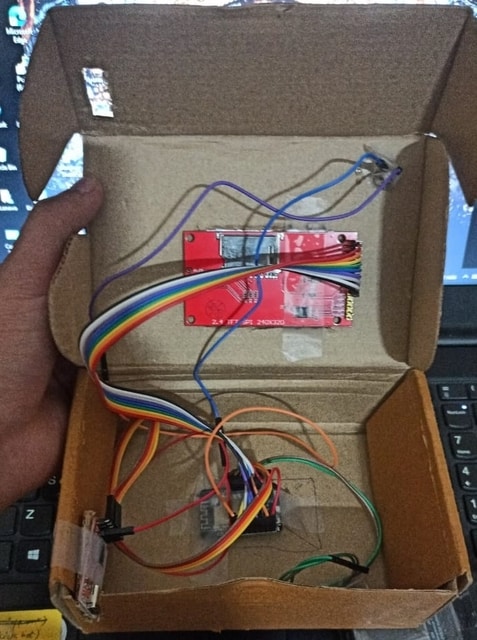
Here is my homemade setup made using card board. All the components are easily placed inside the box.
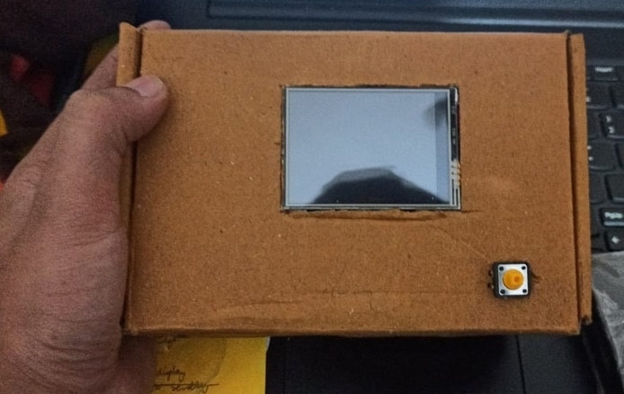
The top side of the box only has TFT LCD Display and a Push Button Switch. The TFT LCD is used for displaying captured images with AI detection.
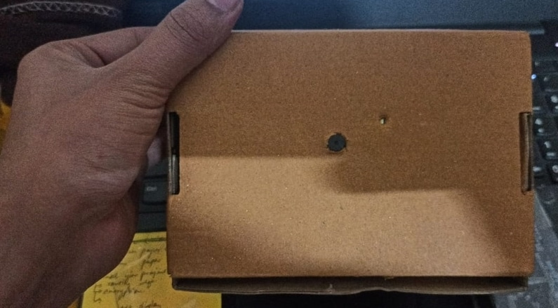
The bottom side of the box only has a camera outlet which is used for the camera function.
PCB Design + Gerber Files + PCB Ordering Online
If you don’t want to assemble the circuit on a breadboard and you want PCB for the project, then here is the PCB for you. The PCB Board for ESP32 CAM AI Board is designed using EasyEDA online Circuit Schematics & PCB designing tool. The schematic looks something like below.

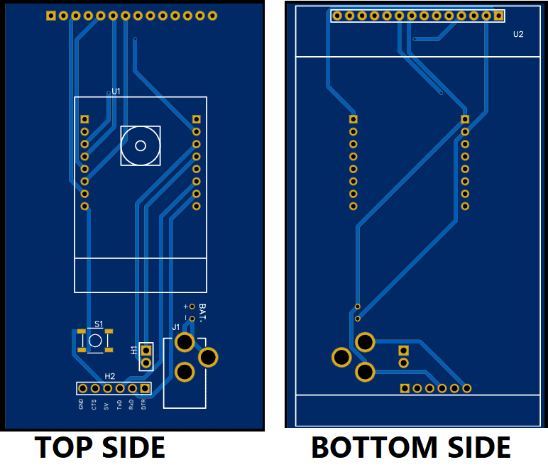
The schematic is then converted to PCB. The top view and bottom view of the PCB are given below.
The Gerber File for the PCB is given below. You can simply download the Gerber File and order the PCB from ALLPCB at 1$ only.
You can use this Gerber file to order high quality PCB for this project. To do that visit the ALLPCB official website by clicking here: https://www.allpcb.com/.

You can now upload the Gerber File by choosing the Quote Now option. From these options, you can choose the Material Type, Dimensions, Quantity, Thickness, Solder Mask Color and other required parameters.

After filling all details, select your country and shipping method. Finally you can place the order.
Flow of Data
Here we have explained the whole workflow, from how the object is detected to displaying labels on the screen. We are having our ESP32 CAM module which captures the image of the environment or the object and then sends it to the TFT screen using SPI protocol so that the image is displayed on the screen.
Now the same image is sent to the NodeJS server which is having the Authentication ID.

Here the engine that detects the Object or creates labels for the object(s) in the image frame is Google Cloud Vision API.
The NodeJS server sends the image to the Vision AI API. But to interact with the API it needs some authentication which is done using the Authentication ID. Once the frame is sent, the API returns the labels to the server, and from the server, these labels are sent to the ESP-CAM and from there, labels are displayed on TFT-Screen.
Arduino Libraries Installation
Now in order to the use TFT screen and read the data from the server we require a few libraries which can be installed using the Arduino library manager. To open Library manager press Ctrl+shift+I, it might take a few seconds to open according to the system specifications. Now in the search bar type the name of libraries and install them.
1. TFT_eSPI by Bodmer: https://github.com/Bodmer/TFT_eSPI
2. TJpg_Decoder by Bodmer: https://github.com/Bodmer/TJpg_Decoder
3. ArduinoJson by Benoit Blanchon: https://github.com/bblanchon/ArduinoJson
Code for TFT Display Test
Now we need to first display the frames captured by the camera on the TFT screen. To do so, upload the code below once the libraries are installed.
|
1 2 3 4 5 6 7 8 9 10 11 12 13 14 15 16 17 18 19 20 21 22 23 24 25 26 27 28 29 30 31 32 33 34 35 36 37 38 39 40 41 42 43 44 45 46 47 48 49 50 51 52 53 54 55 56 57 58 59 60 61 62 63 64 65 66 67 68 69 70 71 72 73 74 75 76 77 78 79 80 81 82 83 84 85 86 87 88 89 90 91 92 93 94 95 96 97 98 99 100 101 102 103 104 105 106 107 108 109 110 111 112 113 114 115 116 117 118 119 120 121 122 123 124 |
#include "esp_camera.h" #include <TJpg_Decoder.h> #include <SPI.h> #include <TFT_eSPI.h> #define PWDN_GPIO_NUM 32 #define RESET_GPIO_NUM -1 #define XCLK_GPIO_NUM 0 #define SIOD_GPIO_NUM 26 #define SIOC_GPIO_NUM 27 #define Y9_GPIO_NUM 35 #define Y8_GPIO_NUM 34 #define Y7_GPIO_NUM 39 #define Y6_GPIO_NUM 36 #define Y5_GPIO_NUM 21 #define Y4_GPIO_NUM 19 #define Y3_GPIO_NUM 18 #define Y2_GPIO_NUM 5 #define VSYNC_GPIO_NUM 25 #define HREF_GPIO_NUM 23 #define PCLK_GPIO_NUM 22 #define GFXFF 1 #define FSB9 &FreeSerifBold9pt7b TFT_eSPI tft = TFT_eSPI(); bool tft_output(int16_t x, int16_t y, uint16_t w, uint16_t h, uint16_t* bitmap) { // Stop further decoding as image is running off bottom of screen if ( y >= tft.height() ) return 0; // This function will clip the image block rendering automatically at the TFT boundaries tft.pushImage(x, y, w, h, bitmap); // This might work instead if you adapt the sketch to use the Adafruit_GFX library // tft.drawRGBBitmap(x, y, bitmap, w, h); // Return return 1; } void setup() { Serial.begin(115200); delay(1000); Serial.println(); Serial.println("INIT DISPLAY"); tft.begin(); tft.setRotation(3); tft.setTextColor(0xFFFF, 0x0000); tft.fillScreen(TFT_CYAN); tft.setFreeFont(FSB9); TJpgDec.setJpgScale(1); TJpgDec.setSwapBytes(true); TJpgDec.setCallback(tft_output); Serial.println("INIT CAMERA"); camera_config_t config; config.ledc_channel = LEDC_CHANNEL_0; config.ledc_timer = LEDC_TIMER_0; config.pin_d0 = Y2_GPIO_NUM; config.pin_d1 = Y3_GPIO_NUM; config.pin_d2 = Y4_GPIO_NUM; config.pin_d3 = Y5_GPIO_NUM; config.pin_d4 = Y6_GPIO_NUM; config.pin_d5 = Y7_GPIO_NUM; config.pin_d6 = Y8_GPIO_NUM; config.pin_d7 = Y9_GPIO_NUM; config.pin_xclk = XCLK_GPIO_NUM; config.pin_pclk = PCLK_GPIO_NUM; config.pin_vsync = VSYNC_GPIO_NUM; config.pin_href = HREF_GPIO_NUM; config.pin_sscb_sda = SIOD_GPIO_NUM; config.pin_sscb_scl = SIOC_GPIO_NUM; config.pin_pwdn = PWDN_GPIO_NUM; config.pin_reset = RESET_GPIO_NUM; config.xclk_freq_hz = 10000000; config.pixel_format = PIXFORMAT_JPEG; //init with high specs to pre-allocate larger buffers if(psramFound()){ config.frame_size = FRAMESIZE_QVGA; // 320x240 config.jpeg_quality = 10; config.fb_count = 2; } else { config.frame_size = FRAMESIZE_SVGA; config.jpeg_quality = 12; config.fb_count = 1; } // camera init esp_err_t err = esp_camera_init(&config); if (err != ESP_OK) { Serial.printf("Camera init failed with error 0x%x", err); return; } } camera_fb_t* capture(){ camera_fb_t *fb = NULL; esp_err_t res = ESP_OK; fb = esp_camera_fb_get(); return fb; } void showingImage(){ camera_fb_t *fb = capture(); if(!fb || fb->format != PIXFORMAT_JPEG){ Serial.println("Camera capture failed"); esp_camera_fb_return(fb); return; }else{ TJpgDec.drawJpg(0,0,(const uint8_t*)fb->buf, fb->len); esp_camera_fb_return(fb); } } void loop() { showingImage(); } |
Make sure the IO0 pin is grounded during the uploading of the code. And if Connecting…. Text appears on the log screen followed by “……._______…….______” just press the Reset Button.
Now the image on the screen must be visible.
Google Vision API
Vision API offers powerful pre-trained machine learning models through REST and RPC APIs. Assign labels to images and quickly classify them into millions of predefined categories. Detect objects and faces, read printed and handwritten text, and build valuable metadata into your image catalog.

It also allows developers to easily integrate vision detection features within applications, including image labeling, face, and landmark detection, optical character recognition (OCR), and tagging of explicit content.
NodeJS Installation
Now in order to create a server we will be using NodeJS. To Install latest version of NodeJS from nodejs.org.

From here download the compatible version of the software, according to your system. Make sure that you have downloaded LTS Version.
GCP and API Setup
Before the whole setup makes sure you have added your credit/debit card in GCP, although the project won’t cost even a single penny. Still, because we are using GCP features they require a billing address.
At first, go to Google Cloud Platform(GCP) through the link here. And Create a new project.
- Here click on New Project
- Add a name to the project and organization can be kept as No Organization
Once the Billing is Enabled and Project is Created. Now we must enable the Vision API for your project. To do so go to this link here. And enable the API.
Now we have to create a service account for authentication. Go to this link.
- Select the project created
- Add a name to service account as well as ID(we don’t have to provide the full ID just a name, although the service ID is automatically generated)
- Now click on Create and Continue
- Click the Select a role field.
- Under Quick access, click Basic, then click Owner.
- Click on continue
- Now click on Done
Now we create a service account key:
- In the Cloud Console, click the email address for the service account that you created.
- Click Keys.
- Click Add key, then click Create new key.
- Click Create. A JSON key file is downloaded to your computer.
- Click Close.
Now open a Command prompt and run the command:
First, locate yourself to a directory where you wish to save the project and create a server. Now open the command prompt at that location.
• npm install –save @google-cloud/vision
• set GOOGLE_APPLICATION_CREDENTIALS=KEY_PATH
For example: set GOOGLE_APPLICATION_CREDENTIALS=”/home/user/Downloads/service-account-file.json”
• Now in the same directory create a new file with “.js” extension(say test.js)
• Also create a folder “resources” and in that add an image(that you wish to test for object detection) with the name “test.jpg”
• Now open test.js and paste the code below
|
1 2 3 4 5 6 7 8 9 10 11 12 13 14 15 16 17 18 19 20 21 22 23 24 25 26 27 |
‘use strict’; function main() { // [START vision_quickstart] async function quickstart() { // Imports the Google Cloud client library const vision = require(‘@google-cloud/vision’); // Creates a client const client = new vision.ImageAnnotatorClient(); // Performs label detection on the image file const [result] = await client.labelDetection(‘./resources/test.jpg’); const labels = result.labelAnnotations; console.log(‘Labels:’); labels.forEach(label =>{ console.log(label)}); } quickstart(); // [END vision_quickstart] } process.on(‘unhandledRejection’, err => { console.error(err.message); process.exitCode = 1; }); main(…process.argv.slice(2)); |
• Now run the above code by writing “node test.js” in the command prompt (make sure you are in the right directory)
• You will see the labels printed in the log that is detected in the test.jpg image
Congratulations our major work is done, now we have to do the same using server as esp-cam
• Create a new folder with the name VisionServer, in that create another folder named resources and also a file named server.js
• Open server.js and paste the code below
|
1 2 3 4 5 6 7 8 9 10 11 12 13 14 15 16 17 18 19 20 21 22 23 24 25 26 27 28 29 30 31 32 33 34 35 36 37 38 39 40 41 42 43 44 45 46 47 48 |
var fs = require('fs'); const http = require('http'); const server = http.createServer(); const filePath = './resources/test.jpeg'; server.on('request', (request, response)=>{ if(request.method == 'POST' && request.url === "/imageUpdate"){ var ImageFile = fs.createWriteStream(filePath, {encoding: 'utf8'}); request.on('data', function(data){ ImageFile.write(data); }); request.on('end',async function(){ ImageFile.end(); const labels = await labelAPI(); response.writeHead(200, {'Content-Type' : 'application/json'}); response.end(JSON.stringify(labels)); }); }else{ console.log("error"); response.writeHead(405, {'Content-Type' : 'text/plain'}); response.end(); } }); async function labelAPI() { var o = []; // Imports the Google Cloud client library const vision = require('@google-cloud/vision'); // Creates a client const client = new vision.ImageAnnotatorClient(); // Performs label detection on the image file const [result] = await client.labelDetection(filePath); const labels = result.labelAnnotations; labels.forEach(label => { o.push({description: label.description, score: label.score}); }); return o; } const port = 8888; server.listen(port) console.log(`Listening at ${port}`) |
• Save the code and run it by opening the command prompt and go to the right directory and write ”node server.js”
Final Arduino Code
Here is the final Arduino Code for AI Camera with Google Vision & ESP32 CAM Module. So, open Arduino IDE & paste the code below by doing a few changes.
First add an SSID and password of the network with which your laptop is connected.
|
1 2 |
const char* ssid = "**********"; const char* password = "**********"; |
Now we have to update the IP address of the server, in this case, our computer is our server thus updating its IP address as in the following line of code.
|
1 |
client.begin("http://192.168.116.56:8888/imageUpdate"); |
Here is the final code that you have to upload to the ESP32 CAM Board.
|
1 2 3 4 5 6 7 8 9 10 11 12 13 14 15 16 17 18 19 20 21 22 23 24 25 26 27 28 29 30 31 32 33 34 35 36 37 38 39 40 41 42 43 44 45 46 47 48 49 50 51 52 53 54 55 56 57 58 59 60 61 62 63 64 65 66 67 68 69 70 71 72 73 74 75 76 77 78 79 80 81 82 83 84 85 86 87 88 89 90 91 92 93 94 95 96 97 98 99 100 101 102 103 104 105 106 107 108 109 110 111 112 113 114 115 116 117 118 119 120 121 122 123 124 125 126 127 128 129 130 131 132 133 134 135 136 137 138 139 140 141 142 143 144 145 146 147 148 149 150 151 152 153 154 155 156 157 158 159 160 161 162 163 164 165 166 167 168 169 170 171 172 173 174 175 176 177 178 179 180 181 182 183 184 185 186 187 188 189 190 191 192 193 194 195 196 197 198 199 200 201 202 203 204 205 206 207 208 209 210 211 212 213 214 215 216 217 218 219 220 221 222 223 224 225 226 227 228 229 230 231 232 233 234 235 236 237 238 239 240 241 242 243 |
#include "esp_camera.h" #include <TJpg_Decoder.h> #include <SPI.h> #include <TFT_eSPI.h> #include <WiFi.h> #include <HTTPClient.h> #include <ArduinoJson.h> #define PWDN_GPIO_NUM 32 #define RESET_GPIO_NUM -1 #define XCLK_GPIO_NUM 0 #define SIOD_GPIO_NUM 26 #define SIOC_GPIO_NUM 27 #define Y9_GPIO_NUM 35 #define Y8_GPIO_NUM 34 #define Y7_GPIO_NUM 39 #define Y6_GPIO_NUM 36 #define Y5_GPIO_NUM 21 #define Y4_GPIO_NUM 19 #define Y3_GPIO_NUM 18 #define Y2_GPIO_NUM 5 #define VSYNC_GPIO_NUM 25 #define HREF_GPIO_NUM 23 #define PCLK_GPIO_NUM 22 #define GFXFF 1 #define FSB9 &FreeSerifBold9pt7b TFT_eSPI tft = TFT_eSPI(); const char* ssid = "**********"; const char* password = "**********"; const unsigned long timeout = 30000; // 30 seconds const int buttonPin = 4; // the number of the pushbutton pin int buttonState; int lastButtonState = LOW; unsigned long lastDebounceTime = 0; // the last time the output pin was toggled unsigned long debounceDelay = 50; // the debounce time; increase if the output flickers bool isNormalMode = true; bool tft_output(int16_t x, int16_t y, uint16_t w, uint16_t h, uint16_t* bitmap) { // Stop further decoding as image is running off bottom of screen if ( y >= tft.height() ) return 0; // This function will clip the image block rendering automatically at the TFT boundaries tft.pushImage(x, y, w, h, bitmap); // This might work instead if you adapt the sketch to use the Adafruit_GFX library // tft.drawRGBBitmap(x, y, bitmap, w, h); // Return return 1; } void setup() { Serial.begin(115200); delay(1000); Serial.println(); pinMode(buttonPin, INPUT); Serial.println("INIT DISPLAY"); tft.begin(); tft.setRotation(3); tft.setTextColor(0xFFFF, 0x0000); tft.fillScreen(TFT_YELLOW); tft.setFreeFont(FSB9); TJpgDec.setJpgScale(1); TJpgDec.setSwapBytes(true); TJpgDec.setCallback(tft_output); Serial.println("INIT CAMERA"); camera_config_t config; config.ledc_channel = LEDC_CHANNEL_0; config.ledc_timer = LEDC_TIMER_0; config.pin_d0 = Y2_GPIO_NUM; config.pin_d1 = Y3_GPIO_NUM; config.pin_d2 = Y4_GPIO_NUM; config.pin_d3 = Y5_GPIO_NUM; config.pin_d4 = Y6_GPIO_NUM; config.pin_d5 = Y7_GPIO_NUM; config.pin_d6 = Y8_GPIO_NUM; config.pin_d7 = Y9_GPIO_NUM; config.pin_xclk = XCLK_GPIO_NUM; config.pin_pclk = PCLK_GPIO_NUM; config.pin_vsync = VSYNC_GPIO_NUM; config.pin_href = HREF_GPIO_NUM; config.pin_sscb_sda = SIOD_GPIO_NUM; config.pin_sscb_scl = SIOC_GPIO_NUM; config.pin_pwdn = PWDN_GPIO_NUM; config.pin_reset = RESET_GPIO_NUM; config.xclk_freq_hz = 10000000; config.pixel_format = PIXFORMAT_JPEG; //init with high specs to pre-allocate larger buffers if(psramFound()){ config.frame_size = FRAMESIZE_QVGA; // 320x240 config.jpeg_quality = 10; config.fb_count = 2; } else { config.frame_size = FRAMESIZE_SVGA; config.jpeg_quality = 12; config.fb_count = 1; } // camera init esp_err_t err = esp_camera_init(&config); if (err != ESP_OK) { Serial.printf("Camera init failed with error 0x%x", err); return; } } bool wifiConnect(){ unsigned long startingTime = millis(); WiFi.begin(ssid, password); while(WiFi.status() != WL_CONNECTED){ delay(500); if((millis() - startingTime) > timeout){ return false; } } return true; } void buttonEvent(){ int reading = digitalRead(buttonPin); if (reading != lastButtonState) { lastDebounceTime = millis(); } if ((millis() - lastDebounceTime) > debounceDelay) { if (reading != buttonState) { buttonState = reading; if (buttonState == HIGH) { isNormalMode = !isNormalMode; //Additional Code if(!isNormalMode) sendingImage(); // } } } lastButtonState = reading; } camera_fb_t* capture(){ camera_fb_t *fb = NULL; esp_err_t res = ESP_OK; fb = esp_camera_fb_get(); return fb; } void showingImage(){ camera_fb_t *fb = capture(); if(!fb || fb->format != PIXFORMAT_JPEG){ Serial.println("Camera capture failed"); esp_camera_fb_return(fb); return; }else{ TJpgDec.drawJpg(0,0,(const uint8_t*)fb->buf, fb->len); esp_camera_fb_return(fb); } } void parsingResult(String response){ DynamicJsonDocument doc(1024); deserializeJson(doc, response); JsonArray array = doc.as<JsonArray>(); int yPos = 4; //tft.setRotation(1); for(JsonVariant v : array){ JsonObject object = v.as<JsonObject>(); const char* description = object["description"]; float score = object["score"]; String label = ""; label += description; label += ":"; label += score; tft.drawString(label, 8, yPos, GFXFF); yPos += 16; } //tft.setRotation(3); } void postingImage(camera_fb_t *fb){ HTTPClient client; client.begin("http://192.168.116.56:8888/imageUpdate"); client.addHeader("Content-Type", "image/jpeg"); int httpResponseCode = client.POST(fb->buf, fb->len); if(httpResponseCode == 200){ String response = client.getString(); parsingResult(response); }else{ //tft.setRotation(1); //Error tft.drawString("Check Your Server!!!", 8, 4, GFXFF); //tft.setRotation(3); } client.end(); WiFi.disconnect(); } void sendingImage(){ camera_fb_t *fb = capture(); if(!fb || fb->format != PIXFORMAT_JPEG){ Serial.println("Camera capture failed"); esp_camera_fb_return(fb); return; }else{ TJpgDec.drawJpg(0,0,(const uint8_t*)fb->buf, fb->len); //tft.setRotation(1); tft.drawString("Wifi Connecting!", 8, 4, GFXFF); //tft.setRotation(3); if(wifiConnect()){ //tft.drawString("Wifi Connected!", 8, 4, GFXFF); TJpgDec.drawJpg(0,0,(const uint8_t*)fb->buf, fb->len); postingImage(fb); }else{ //tft.setRotation(1); tft.drawString("Check Wifi credential!", 8, 4, GFXFF); //tft.setRotation(3); } esp_camera_fb_return(fb); } } void loop() { buttonEvent(); if(isNormalMode) showingImage(); } |
Testing DIY AI Camera using Google Vision & ESP32 CAM
Now when you press the button for 1 second the flash will appear and the image is clicked.
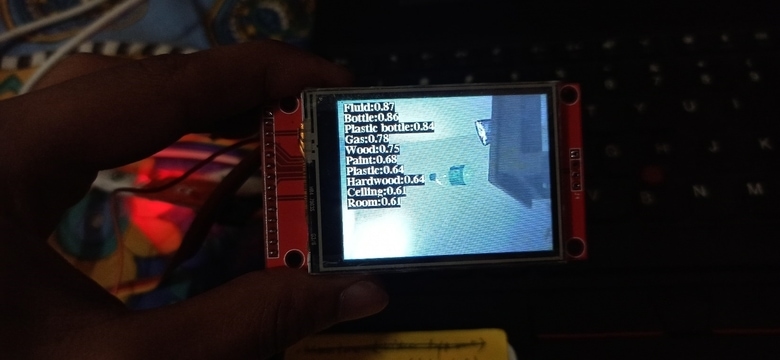
And after a few seconds the labels appear, congratulations the AI camera started working.
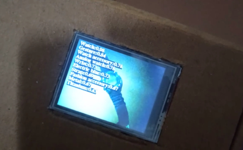
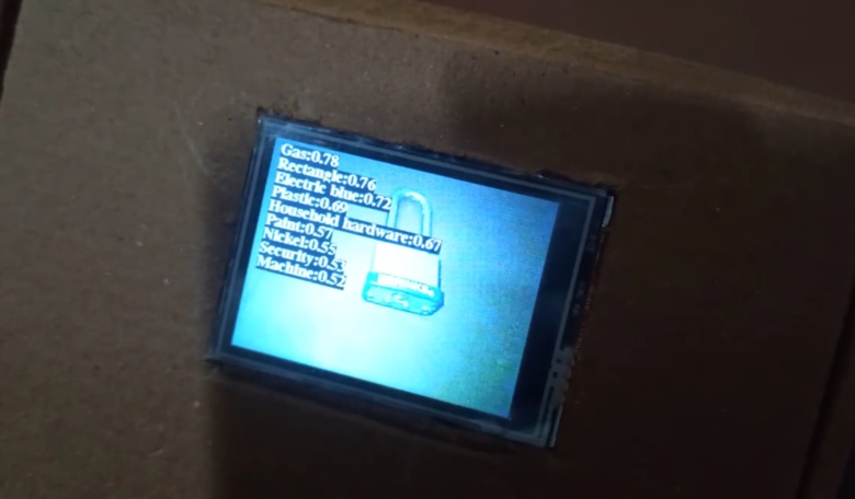
Here are the samples of other images taken with this DIY AI Camera.
Video Tutorial & Guide

 & Live Dashboard")


1 Comment
I found an error when uploading the program. error compiling for board esp32 cam wrover module. do you know the cause?