

Overview
In this project, you’ll learn how to create a Density Based 4 way Traffic Light Controller project using an ESP32 microcontroller and ultrasonic sensors, with integration into the Blynk IoT platform for real-time monitoring and control. Earlier we made Simple Traffic Light Controller using Raspberry Pi Pico.
The primary goal of this project is to create a smart traffic management system that optimizes signal timing based on the density of traffic. Rather than following a fixed timing schedule, this system dynamically adjusts the signal changes, ensuring that if no vehicles are present at a signal, it will be skipped in favor of the next one, thereby reducing unnecessary waiting times and improving traffic flow.
At the heart of the system lies the ESP32, a powerful and versatile microcontroller that reads data from HC-SR04 ultrasonic sensors placed at each signal. These sensors measure the distance to the nearest object, providing a reliable estimation of vehicle presence and proximity at each traffic signal. Based on the Ultrasonic Sensor data, the light signalling functions. Additionally, this system utilizes the Blynk IoT platform to offer a user-friendly interface that displays the system status.
Bill of Materials
The following are the components required for making Smart Density Based Traffic Light Controller Project with ESP32. You can purchase all the components online from given links.
| S.N. | Components | Quantity | Purchase Links |
|---|---|---|---|
| 1 | ESP32 WiFi Module | 1 | Amazon | AliExpress | SunFounder |
| 2 | Ultrasonic Sensor HC-SR04 | 4 | Amazon | AliExpress | SunFounder |
| 3 | Red LED | 4 | Amazon | AliExpress | SunFounder |
| 4 | Yellow LED | 4 | Amazon | AliExpress | SunFounder |
| 5 | Green LED | 4 | Amazon | AliExpress | SunFounder |
| 6 | Resistor 220-ohm | 12 | Amazon | AliExpress| SunFounder |
| 7 | Connecting Wires | 30 | Amazon | AliExpress | SunFounder |
| 8 | Micro-USB Cable | 1 | Amazon | AliExpress |
| 9 | Breadboard | 1 | Amazon | AliExpress | SunFounder |
Algorithm & Working of the Project
The following flowchart shows the algorithm used for making a Smart Density Based Traffic Light Controller Project.

The working of project is divided into three steps:
- Normal Operation with Traffic at All Signals: When traffic is detected at each of the four signals, the system operates in a standard cycle. It sequentially controls each traffic signal, allowing for a regulated flow of vehicles. The system transitions from one signal to the next, ensuring that each direction is given a green light in turn.
- Adaptive Skipping of Signals Without Traffic: The system actively monitors the presence of vehicles at each signal using ultrasonic sensors. If it detects an absence of traffic at a particular signal, the system will adaptively skip this signal to reduce unnecessary waiting times. For instance, if it’s currently allowing traffic at signal 1 and detects no vehicles waiting at signals 2 and 3, it will proceed directly to signal 4 after completing the cycle at signal 1.
- Idle State During Absence of Traffic: If the ultrasonic sensors do not detect traffic at any of the four signals, the system enters a standby mode at the current signal. It will remain in this state until vehicles are detected at any signal. Once traffic is detected, the system resumes its operation, starting the cycle with the signal where traffic was identified.
Circuit Digram & Connection
Let us take a look at the circuit diagram of “Density Based Traffic Light Controller project using ESP32“. The circuit is designed using the frtizing software.

In the diagram, each connection is color-coded, representing different connections, ensuring clarity and aiding in the setup and troubleshooting of the circuit.
The ESP32 is the central processing unit that manages all components, including traffic lights and ultrasonic sensors. It is connected to a power source, Wi-Fi network, and other peripherals for complete control.
Each signal has three LEDs representing the Red, Yellow, and Green lights which are connected as follows.
| Signal Number | Red LED | Yellow LED | Green LED | GND |
|---|---|---|---|---|
| Signal 1 | GPIO 26 | GPIO 25 | GPIO 33 | Connect to GND |
| Signal 2 | GPIO 19 | GPIO 18 | GPIO 5 | Connect to GND |
| Signal 3 | GPIO 32 | GPIO 3 | GPIO 21 | Connect to GND |
| Signal 4 | GPIO 17 | GPIO 16 | GPIO 15 | Connect to GND |
There are 4 Ultrasonic sensors utilized to measure the traffic density at each signal. Refer to ESP32 & HC-SR04 interfacing guide to learn about Ultrasonic Sensor. The Ultrasonic Sensor HC-SR04 is connected to ESP32 as follows.
| Sensor Number | Trigger Pin | Echo Pin | VCC | GND |
|---|---|---|---|---|
| Sensor 1 | GPIO 13 | GPIO 12 | Connect to 5V | Connect to GND |
| Sensor 2 | GPIO 27 | GPIO 14 | Connect to 5V | Connect to GND |
| Sensor 3 | GPIO 22 | GPIO 23 | Connect to 5V | Connect to GND |
| Sensor 4 | GPIO 2 | GPIO 4 | Connect to 5V | Connect to GND |
All the components are powered by a 5V supply. Make sure that the ground of the power supply is connected to the ground of the ESP32.
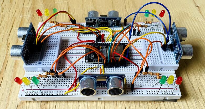
You can use a pair of breadboard for assembly as ESP32 doesn’t fit into a single breadboard. Use smaller breadboard to fit two ultrasonic sensors in opposite directions. Also make sure that all components are correctly connected as per the diagram to ensure the proper functionality of the density based traffic light controller project.
Setting Up Blynk Application
Visit blynk.cloud and create a Blynk account on the Blynk website. Or you can simply sign in using the registered Email ID.
Click on +New Template.
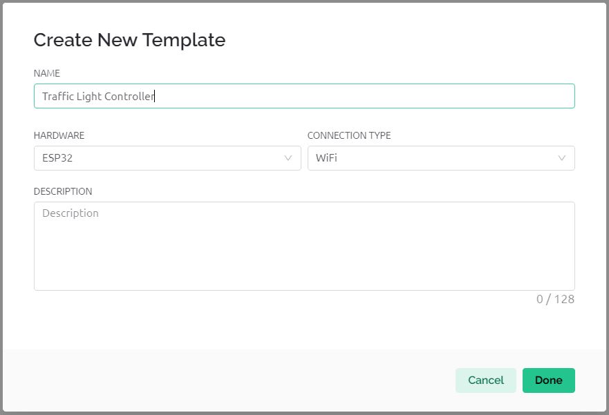
Give any name to the Hardware such as “Traffic Light Controller“. Choose the Hardware type as ESP32 and the connection type as WiFi.
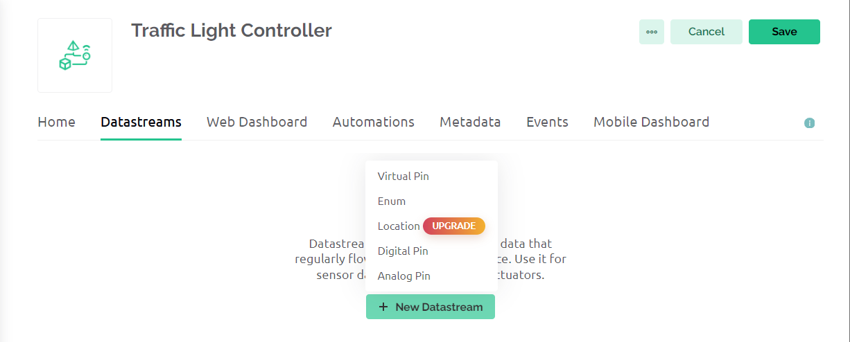
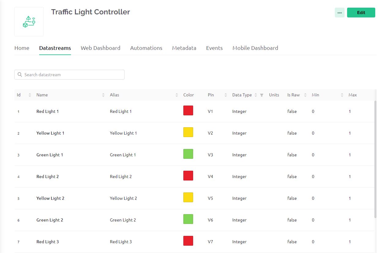
Now we need to set up Datastreams. Therefore Click on +New Datastreams and Select Virtual Pin.
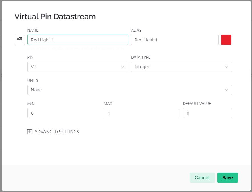
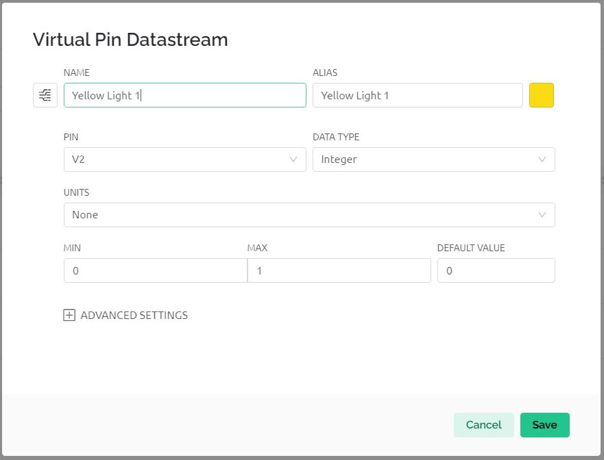
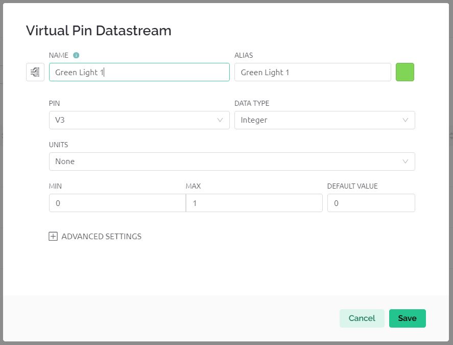
Create datastreams for Red Light 1, Yellow Light 1, and Green Light 1 and assign the virtual pins as V1, V2, and V3 respectively.
In the same way create data streams for Red Light 2, Yellow Light 2, and Green Light 2 and assign the virtual pins as V4, V5, and V6 respectively.
Do the same for 3rd Traffic Lights and 4th Traffic Lights. So the total number of data streams will be 12.
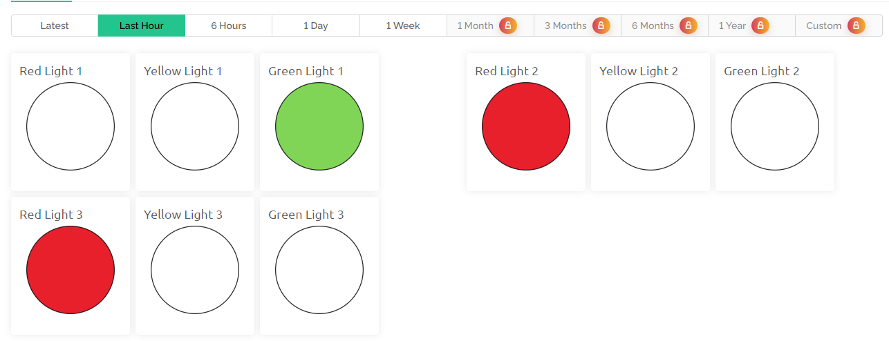
Now go to the Dashboard section and set up the dashboard.
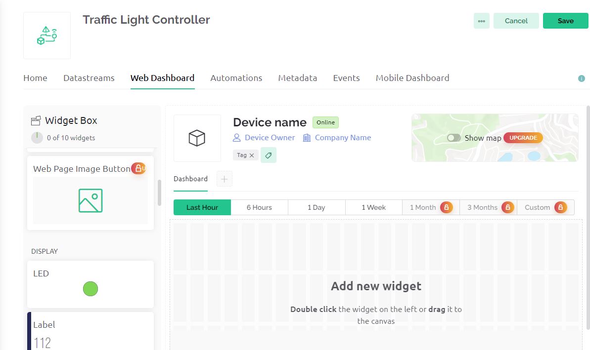
For all the 4 Red LEDs, 4 Yellow LEDs, and 4 Green LEDs link all the widgets with the datastreams and click on save.
With the free version, you can only use 10 widgets. If you want to monitor more than 12 data streams you need to upgrade the app. In my case, I am using the free version. Therefore I am monitoring using only 3 traffic lights which will be 9 LEDs.
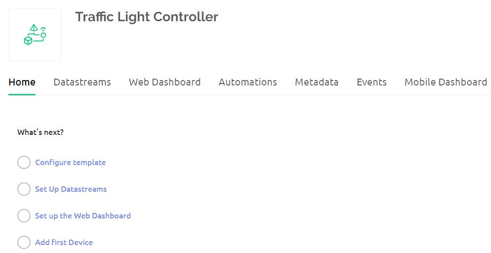
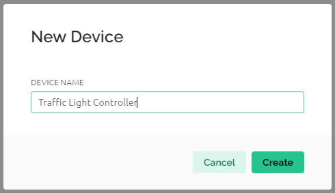
Go to the Home and click on Add Device. Name the Device “Traffic Light Controller” and Click on Create.
After the device is successfully created, you will get the device ID and Authentication Token. The Authentication Token will be used in the code.
Source Code/Program
The complete code for the Project “Density Based Traffic Light Controller with ESP32 & Blynk” is written in Arduino IDE.
You need to add Blynk Library to your Arduino IDE first.
In the code below, you need to change the WiFi SSID, Password and Blynk Authentication token from these lines. Replace it with your credentials.
|
1 2 3 |
char auth[] = "************************"; char ssid[] = "************************"; char pass[] = "************************"; |
Here is the final code for the project. Copy it and paste it on your Arduino IDE editor. Make necessary changes in the code as mentioned aboved.
|
1 2 3 4 5 6 7 8 9 10 11 12 13 14 15 16 17 18 19 20 21 22 23 24 25 26 27 28 29 30 31 32 33 34 35 36 37 38 39 40 41 42 43 44 45 46 47 48 49 50 51 52 53 54 55 56 57 58 59 60 61 62 63 64 65 66 67 68 69 70 71 72 73 74 75 76 77 78 79 80 81 82 83 84 85 86 87 88 89 90 91 92 93 94 95 96 97 98 99 100 101 102 103 104 105 106 107 108 109 110 111 112 113 114 115 116 117 118 119 120 121 122 123 124 125 126 127 128 129 130 131 132 133 134 135 136 137 138 139 140 141 142 143 144 145 146 147 148 149 150 151 152 153 154 155 156 157 158 159 160 161 162 163 164 165 166 167 168 169 170 171 172 173 174 175 176 177 178 179 180 181 182 183 184 185 186 187 188 189 190 191 192 193 194 195 196 197 198 199 200 201 202 203 204 |
#define BLYNK_TEMPLATE_ID "************************" #define BLYNK_TEMPLATE_NAME "Traffic Light Controller" #include <WiFi.h> #include <WiFiClient.h> #include <BlynkSimpleEsp32.h> char auth[] = "************************"; char ssid[] = "************************"; char pass[] = "************************"; // GPIO pins for each traffic signal light (red, yellow, green) int signal1[] = {26, 25, 33}; int signal2[] = {19, 18, 5}; int signal3[] = {32, 3, 21}; int signal4[] = {17, 16, 15}; // Timing delays for light changes (milliseconds) int redDelay = 5000; int yellowDelay = 2000; // Ultrasonic sensor pins int triggerpin1 = 13; int echopin1 = 12; int triggerpin2 = 27; int echopin2 = 14; int triggerpin3 = 22; int echopin3 = 23; int triggerpin4 = 2; int echopin4 = 4; long duration; // Time for ultrasonic signal to return int S1, S2, S3, S4; // Distance measurements from each sensor int t = 5; // Threshold distance to check for traffic presence void setup() { Serial.begin(115200); Blynk.begin(auth, ssid, pass); // Initialize traffic signal LEDs as outputs for (int i = 0; i < 3; i++) { pinMode(signal1[i], OUTPUT); pinMode(signal2[i], OUTPUT); pinMode(signal3[i], OUTPUT); pinMode(signal4[i], OUTPUT); } // Initialize ultrasonic sensor pins pinMode(triggerpin1, OUTPUT); pinMode(echopin1, INPUT); pinMode(triggerpin2, OUTPUT); pinMode(echopin2, INPUT); pinMode(triggerpin3, OUTPUT); pinMode(echopin3, INPUT); pinMode(triggerpin4, OUTPUT); pinMode(echopin4, INPUT); } void loop() { Blynk.run(); // Measure distance from each ultrasonic sensor S1 = readDistance(triggerpin1, echopin1); S2 = readDistance(triggerpin2, echopin2); S3 = readDistance(triggerpin3, echopin3); S4 = readDistance(triggerpin4, echopin4); // Check and update the status of each traffic signal if (S1 < t) { signal1Function(); } else if (S2 < t) { signal2Function(); } else if (S3 < t) { signal3Function(); } else if (S4 < t) { signal4Function(); } // Send updated signal status to Blynk updateBlynk(); // Wait a bit before next loop iteration delay(1000); } int readDistance(int triggerPin, int echoPin) { digitalWrite(triggerPin, LOW); delayMicroseconds(2); digitalWrite(triggerPin, HIGH); delayMicroseconds(10); digitalWrite(triggerPin, LOW); duration = pulseIn(echoPin, HIGH); return duration * 0.034 / 2; // Convert to cm } // Define functions for handling each signal void signal1Function() { controlSignal(signal1, V1, V2, V3); } void signal2Function() { controlSignal(signal2, V4, V5, V6); } void signal3Function() { controlSignal(signal3, V7, V8, V9); } void signal4Function() { controlSignal(signal4, V10, V11, V12); } // Controls the signal light changes and updates Blynk void controlSignal(int signalPins[], int vPinRed, int vPinYellow, int vPinGreen) { lowAll(); // Reset all signals to red before changing the current one digitalWrite(signalPins[0], HIGH); // Turn on red LED Blynk.virtualWrite(vPinRed, 255); delay(redDelay); digitalWrite(signalPins[0], LOW); // Turn off red LED Blynk.virtualWrite(vPinRed, 0); digitalWrite(signalPins[2], HIGH); // Turn on green LED Blynk.virtualWrite(vPinGreen, 255); delay(redDelay); digitalWrite(signalPins[2], LOW); // Turn off green LED Blynk.virtualWrite(vPinGreen, 0); digitalWrite(signalPins[1], HIGH); // Turn on yellow LED Blynk.virtualWrite(vPinYellow, 255); delay(yellowDelay); digitalWrite(signalPins[1], LOW); // Turn off yellow LED Blynk.virtualWrite(vPinYellow, 0); } // Check if there is traffic at any signal bool anyTraffic() { return (S1 < t || S2 < t || S3 < t || S4 < t); } // Set all signals to red void lowAll() { for (int i = 0; i < 4; i++) { digitalWrite(signal1[0], HIGH); digitalWrite(signal1[1], LOW); digitalWrite(signal1[2], LOW); digitalWrite(signal2[0], HIGH); digitalWrite(signal2[1], LOW); digitalWrite(signal2[2], LOW); digitalWrite(signal3[0], HIGH); digitalWrite(signal3[1], LOW); digitalWrite(signal3[2], LOW); digitalWrite(signal4[0], HIGH); digitalWrite(signal4[1], LOW); digitalWrite(signal4[2], LOW); } } // Update Blynk with the current status of traffic signals void updateBlynk() { Blynk.virtualWrite(V1, digitalRead(signal1[0]) == HIGH ? 255 : 0); // Signal 1 Red Blynk.virtualWrite(V2, digitalRead(signal1[1]) == HIGH ? 255 : 0); // Signal 1 Yellow Blynk.virtualWrite(V3, digitalRead(signal1[2]) == HIGH ? 255 : 0); // Signal 1 Green Blynk.virtualWrite(V4, digitalRead(signal2[0]) == HIGH ? 255 : 0); // Signal 2 Red Blynk.virtualWrite(V5, digitalRead(signal2[1]) == HIGH ? 255 : 0); // Signal 2 Yellow Blynk.virtualWrite(V6, digitalRead(signal2[2]) == HIGH ? 255 : 0); // Signal 2 Green Blynk.virtualWrite(V7, digitalRead(signal3[0]) == HIGH ? 255 : 0); // Signal 3 Red Blynk.virtualWrite(V8, digitalRead(signal3[1]) == HIGH ? 255 : 0); // Signal 3 Yellow Blynk.virtualWrite(V9, digitalRead(signal3[2]) == HIGH ? 255 : 0); // Signal 3 Green Blynk.virtualWrite(V10, digitalRead(signal4[0]) == HIGH ? 255 : 0); // Signal 4 Red Blynk.virtualWrite(V11, digitalRead(signal4[1]) == HIGH ? 255 : 0); // Signal 4 Yellow Blynk.virtualWrite(V12, digitalRead(signal4[2]) == HIGH ? 255 : 0); // Signal 4 Green } |
After making necessary changes, you can select the ESP32 Dev Module from the board list and also the COM port. Then hit the upload button to upload the code.
Testing & Demo: Density Based Traffic Light Controller with ESP32 & Blynk

After uploading the code, power up the ESP32 and let it initialize the GPIO pins for the LEDs and ultrasonic sensors.
The ultrasonic sensors continuously measure the distance to detect vehicles near each signal.
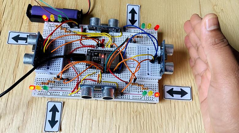
Based on sensor readings, the ESP32 controls the traffic lights, ensuring efficient traffic flow by dynamically managing the signals.

The ESP32 also communicates with the Blynk IoT platform for real-time monitoring and control, enabling a smart traffic management system.
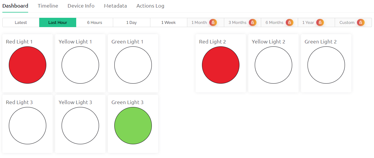
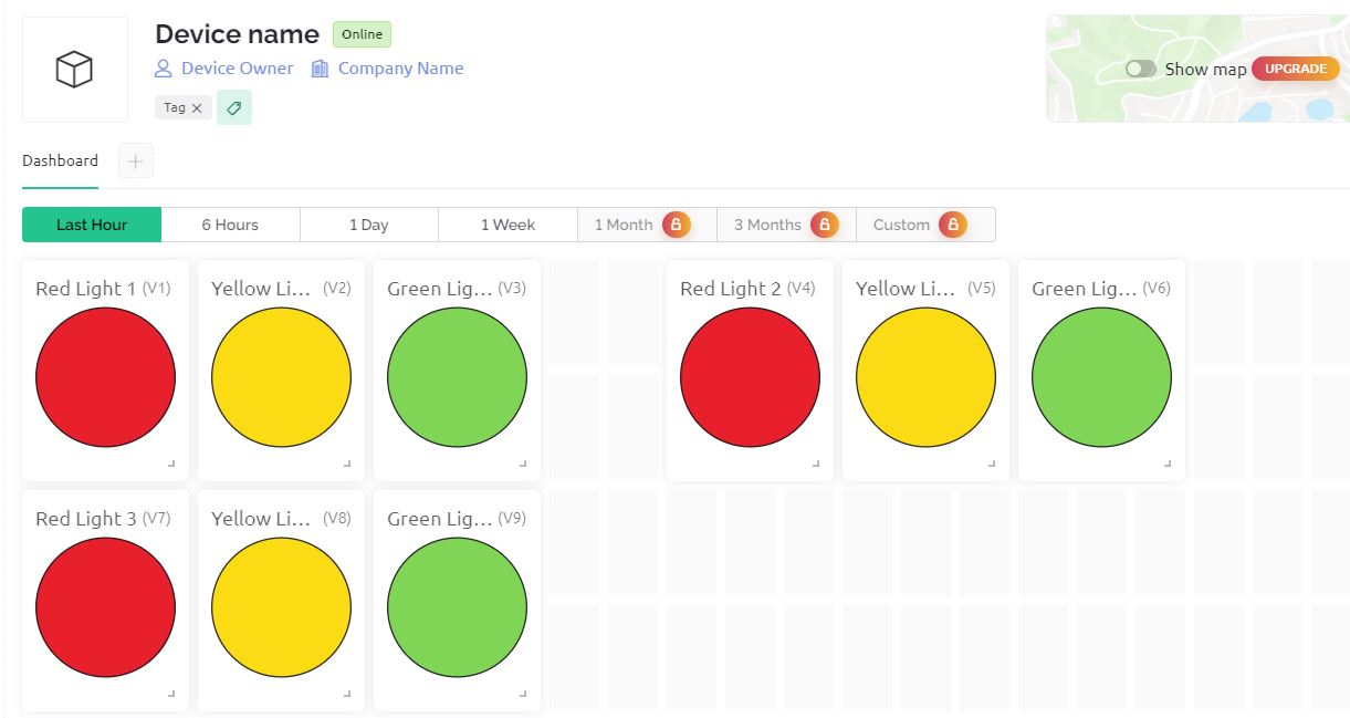
The first and 2nd signal red light is turned on and 3rd light appears to be green.
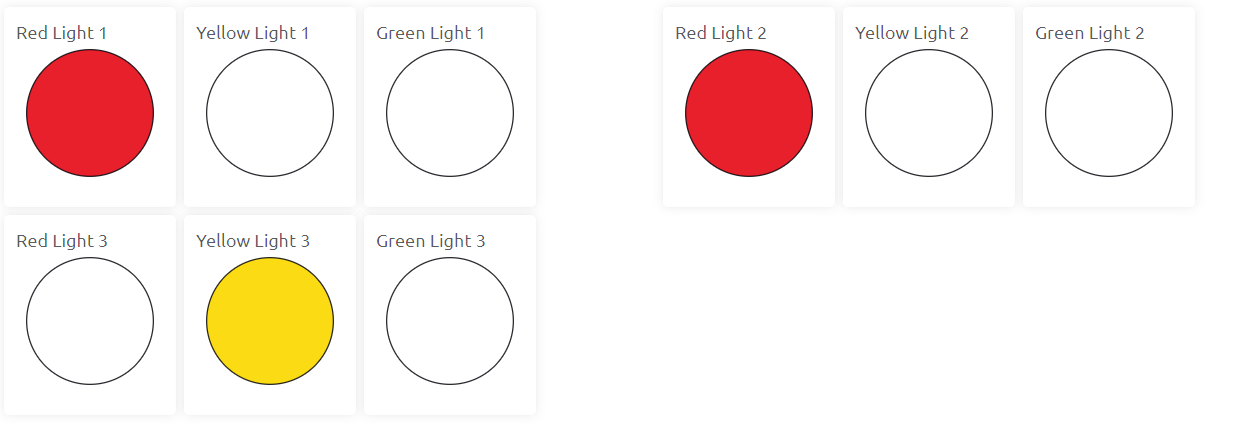
The first and 2nd signal red light is turned on and 3rd light appears to be Yellow. The light remains on for two seconds.
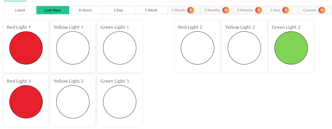
In other instances, the first and 3rd signal red light is turned on and 2nd light appears to be Green. The light remains on for two seconds.
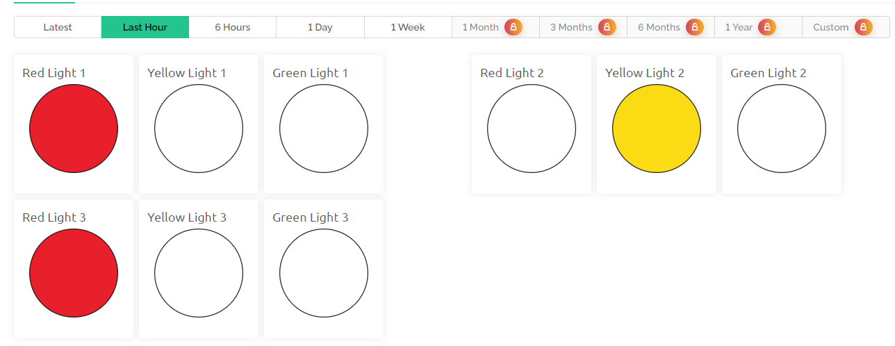
Based on the Ultrasonic Distance and traffic light conditions the light changes and can be observed on Blynk App Dashboard.
This project could be made more better by integrating an alarm system and a camera to capture images of vehicles moving during a red signal would enhance this traffic control system significantly, making it more secure and efficient.
 & Live Dashboard")


