

Overview
In this project, you will learn how to make IoT Based RFID Attendance System using Arduino Node MCU ESP8266 Arduino & Adafruit.io Platform using the MQTT broker. So we will use RFID MFRC522, Arduino Nano, and Node MCU ESP-12E Board. Arduino and RFID scanner scans the RFID cards and then logs the data to the Adafruit IO cloud platform with the help of the ESP8266 Wi-Fi module. This information can be displayed in the Adafruit IO dashboard and can be accessed by the required authorities to view and analyze the attendance over the internet from anywhere at any time. So let’s get started.
But before getting started, you can view our previous RFID Attendance System Project, Using Arduino:
1. RFID Based Attendance System using Arduino, RTC & LCD Display
2. RFID RC522 Based Attendance System Using Arduino with Data Logger
Components Required
The components required for making IoT Based RFID Attendance System project are given below. All the components can be purchased from Amazon.
| S.N. | Components | Quantity | Purchase Links |
|---|---|---|---|
| 1 | NodeMCU ESP8266 Board | 1 | Amazon | AliExpress |
| 2 | Arduino UNO Board | 1 | Amazon | AliExpress |
| 3 | RC522 RFID Module | 1 | Amazon | AliExpress |
| 4 | 13.56 MHz RFID Cards | 5-10 | Amazon | AliExpress |
| 5 | Connecting Wires | 10-20 | Amazon | AliExpress |
| 6 | Breadboard | 1 | Amazon | AliExpress |
Circuit Diagram & Connections
We just need Arduino Nano, NodeMCU Board, and MFRC522 RFID. So the connection diagram is exactly the same as shown in the figure.

Connect the SDA pin of RFID to Arduino Digital pin 10. Similarly Connect SCK to D13, MOSI to D11, MISO to D12, GND to GND, RST pin to D9 and supply 3.3V power using 3.3V Pins. IRQ is not connected. Similarly connect NodeMCU TX, RX pins to Arduino D2, D3 Pins respectively. Also, supply Power to Node MCU by connecting its VCC and GND Pins.
Hardware Setup
So here is our hardware complete setup. You can see Arduino Nano, Nodemcu board, and MFRC522 RFID scanner here.

All are connected as per the circuit diagram simply on a breadboard. MFRC522 is an SPI Module connected to Arduino. Nodemcu is connected via UART pins. There are few RFID cards, actually a total of 6 Cards for 6 people. All of these cards has a frequency of 13.56 MHz.
Setting Up Adafruit.io Account
Adafruit.io is an open data platform that allows you to aggregate, visualize, and analyze live data on the cloud. Using Adafruit.io, you can upload, display, and monitor your data over the internet, and make your project IoT enabled.
For Adafruit setup, the first thing you will need to do is to sign up for Adafruit. To sign up go to Adafruit IO’s site https://io.adafruit.com/ and click on ‘Get started for Free’ on the top right of the screen. After this, a window will pop up where you need to fill your details.

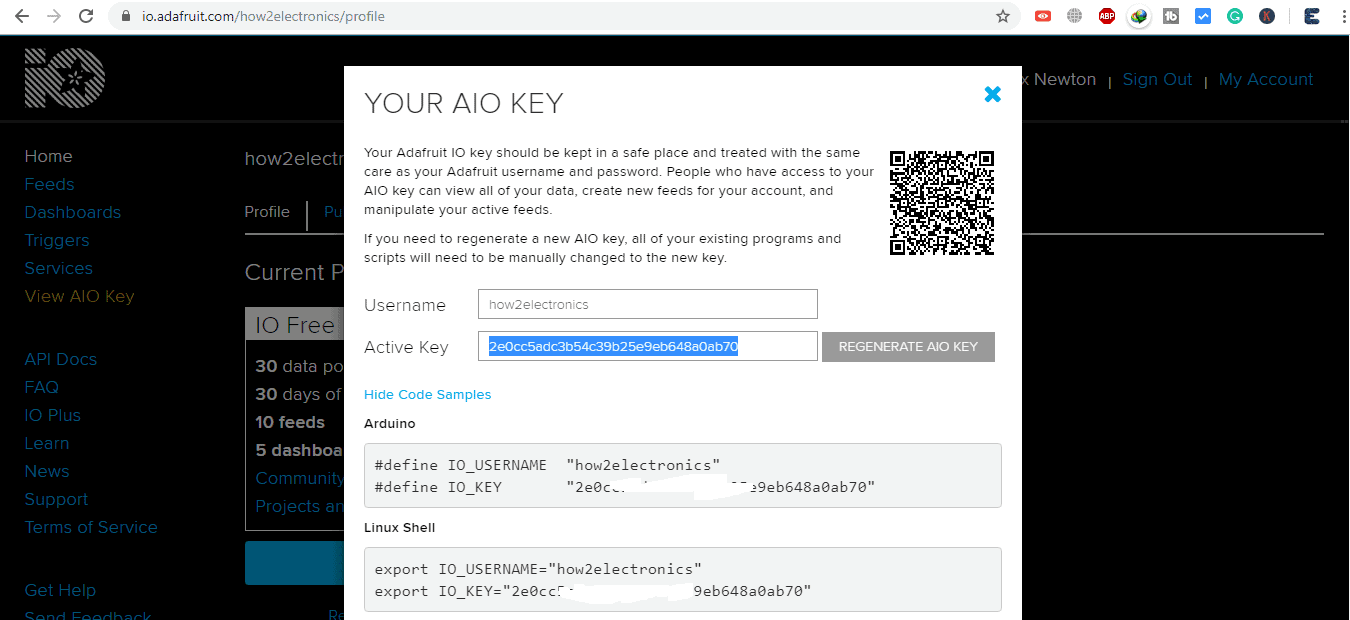
So once the account is created simply go back to https://io.adafruit.com/. On the left side click on view AIO Key. From here you need to copy the username and also the AIO Key. So copy these keys simply on notepad as you will need this later to use in the program.
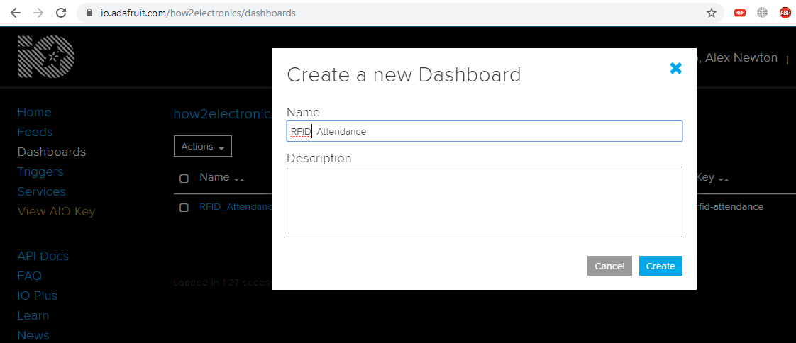
Now on the left side, click on the dashboard and create a new dashboard using any name like for example RFID_Attendance. You may or may not give the description. So the dashboard is created.
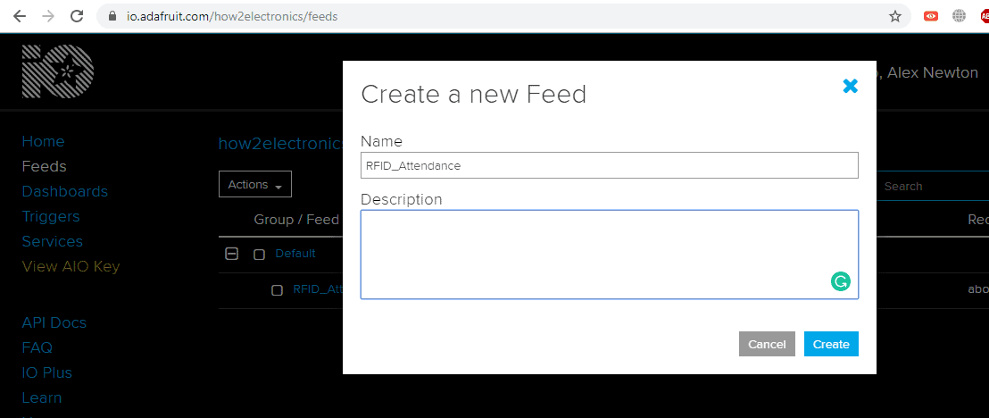
Now similarly go to feeds and create a new feed. Give the name to it. Also, copy this name (to notepad) that you have given to it, as we will also require this later.
Source Code/program
The project IoT Based RFID Attendance System Using Arduino ESP8266 & Adafruit.io is made using NodeMCU & Arduino Board. So, we have two codes one for arduino UNO/Nano and other for NodeMCU. You need to upload these both codes to Arduino and NodeMCU.
Code for Arduino Board
You need MFRC522 Library. Download the library from here: MFRC522 Library
|
1 2 3 4 5 6 7 8 9 10 11 12 13 14 15 16 17 18 19 20 21 22 23 24 25 26 27 28 29 30 31 32 33 34 35 36 37 38 39 40 41 42 43 44 45 46 47 48 49 50 51 52 53 54 55 56 57 58 59 60 61 62 63 64 65 66 67 68 69 70 71 72 73 74 75 76 77 78 79 80 81 82 83 84 85 86 87 88 89 90 91 |
#include <SPI.h> #include <MFRC522.h> #include "SoftwareSerial.h" #define SS_PIN 10 #define RST_PIN 9 MFRC522 mfrc522(SS_PIN, RST_PIN); // Create MFRC522 instance. SoftwareSerial ser(2,3); // RX, TX void setup() { Serial.begin(9600); // Initiate a serial communication ser.begin (115200); SPI.begin(); // Initiate SPI bus mfrc522.PCD_Init(); // Initiate MFRC522 Serial.println("Put RFID Card to Scan..."); Serial.println(); } void loop() { // Look for new cards if ( ! mfrc522.PICC_IsNewCardPresent()) { return; } // Select one of the cards if ( ! mfrc522.PICC_ReadCardSerial()) { return; } //Show UID on serial monitor String content= ""; byte letter; for (byte i = 0; i < mfrc522.uid.size; i++) { content.concat(String(mfrc522.uid.uidByte[i] < 0x10 ? " 0" : " ")); content.concat(String(mfrc522.uid.uidByte[i], HEX)); } Serial.println(); Serial.print("User No./Name: "); content.toUpperCase(); if (content.substring(1) == "E9 9C B0 E3" ) //change here the UID of the card/cards that you want to give access { Serial.println("1-Alex Newton"); ser.write(1); Serial.println(); delay(3000); } if (content.substring(1) == "01 15 C9 1F" ) //change here the UID of the card/cards that you want to give access { Serial.println("2-Tracy Witney"); ser.write(2); Serial.println(); delay(3000); } if (content.substring(1) == "B9 BF 62 1B" ) //change here the UID of the card/cards that you want to give access { Serial.println("3-Lucinda Ambrey"); ser.write(3); Serial.println(); delay(3000); } if (content.substring(1) == "C9 17 AF E3" ) //change here the UID of the card/cards that you want to give access { Serial.println("4-Simon Jones"); ser.write(4); Serial.println(); delay(3000); } if (content.substring(1) == "D9 4D 0C 1B" ) //change here the UID of the card/cards that you want to give access { Serial.println("5-Dimitri Levrock"); ser.write(5); Serial.println(); delay(3000); } if (content.substring(1) == "3B 06 A9 1B" ) //change here the UID of the card/cards that you want to give access { Serial.println("6-Jasmine Joseph"); ser.write(6); Serial.println(); delay(3000); } } |
Code for NodeMCU ESP-12E Board
You need MQTT Library. Download the library from here: MQTT Library
|
1 2 3 4 5 6 7 8 9 10 11 12 13 14 15 16 17 18 19 20 21 22 23 24 25 26 27 28 29 30 31 32 33 34 35 36 37 38 39 40 41 42 43 44 45 46 47 48 49 50 51 52 53 54 55 56 57 58 59 60 61 62 63 64 65 66 67 68 69 70 71 72 73 74 75 76 77 78 79 80 81 82 83 84 85 86 87 88 89 90 91 92 |
#include <ESP8266WiFi.h> #include "Adafruit_MQTT.h" #include "Adafruit_MQTT_Client.h" // WiFi parameters #define WLAN_SSID "Your Wifi SSID" #define WLAN_PASS "Your Wifi Password" // Adafruit IO #define AIO_SERVER "io.adafruit.com" #define AIO_SERVERPORT 1883 #define AIO_USERNAME "Your AIO Username" #define AIO_KEY "Your AIO Key" // Obtained from account info on io.adafruit.com // Create an ESP8266 WiFiClient class to connect to the MQTT server. WiFiClient client; // Setup the MQTT client class by passing in the WiFi client and MQTT server and login details. Adafruit_MQTT_Client mqtt(&client, AIO_SERVER, AIO_SERVERPORT, AIO_USERNAME, AIO_KEY); Adafruit_MQTT_Publish Attendance = Adafruit_MQTT_Publish(&mqtt, AIO_USERNAME "/feeds/RFID_Attendance"); char ID; /*************************** Sketch Code ************************************/ void setup() { Serial.begin(115200); Serial.println(F("Adafruit IO Example")); // Connect to WiFi access point. Serial.println(); Serial.println(); delay(10); Serial.print(F("Connecting to ")); Serial.println(WLAN_SSID); WiFi.begin(WLAN_SSID, WLAN_PASS); while (WiFi.status() != WL_CONNECTED) { delay(500); Serial.print(F(".")); } Serial.println(); Serial.println(F("WiFi connected")); Serial.println(F("IP address: ")); Serial.println(WiFi.localIP()); // connect to adafruit io connect(); } // connect to adafruit io via MQTT void connect() { Serial.print(F("Connecting to Adafruit IO... ")); int8_t ret; while ((ret = mqtt.connect()) != 0) { switch (ret) { case 1: Serial.println(F("Wrong protocol")); break; case 2: Serial.println(F("ID rejected")); break; case 3: Serial.println(F("Server unavail")); break; case 4: Serial.println(F("Bad user/pass")); break; case 5: Serial.println(F("Not authed")); break; case 6: Serial.println(F("Failed to subscribe")); break; default: Serial.println(F("Connection failed")); break; } if(ret >= 0) mqtt.disconnect(); Serial.println(F("Retrying connection...")); delay(5000); } Serial.println(F("Adafruit IO Connected!")); } void loop() { // ping adafruit io a few times to make sure we remain connected if(! mqtt.ping(3)) { // reconnect to adafruit io if(! mqtt.connected()) connect(); } if ( Serial.available() ) { // Update and send only after 1 seconds char a = Serial.read(); ID = a; if (! Attendance.publish(ID)) { //Publish to Adafruit Serial.println(F("Failed")); } else { Serial.println(F("Sent!")); } } } |
Code Explanation
1. Arduino Code:
|
1 2 3 4 5 6 7 |
#include <SPI.h> #include <MFRC522.h> #include "SoftwareSerial.h" #define SS_PIN 10 #define RST_PIN 9 MFRC522 mfrc522(SS_PIN, RST_PIN); // Create MFRC522 instance. SoftwareSerial ser(2,3); // RX, TX |
MFRC522 library is used for the RFID scanner. SDA and RST pins are connected with 10 and 9 pins of Arduino as shown in the circuit diagram.
|
1 2 3 4 5 6 7 8 9 |
void setup() { Serial.begin(9600); // Initiate a serial communication ser.begin (115200); SPI.begin(); // Initiate SPI bus mfrc522.PCD_Init(); // Initiate MFRC522 Serial.println("Put RFID Cards to Scan ......."); Serial.println(); } |
Inside the setup function, we initialize the Serial communication at 9600 and software serial at 115200 baud rate. We have also opened communication with MFRC522.
|
1 2 3 4 5 6 7 8 9 10 11 12 13 14 15 16 17 18 19 20 21 22 23 24 25 26 27 28 29 30 31 32 |
void loop() { // Look for new cards if ( ! mfrc522.PICC_IsNewCardPresent()) { return; } // Select one of the cards if ( ! mfrc522.PICC_ReadCardSerial()) { return; } //Show UID on serial monitor String content= ""; byte letter; for (byte i = 0; i < mfrc522.uid.size; i++) { content.concat(String(mfrc522.uid.uidByte[i] < 0x10 ? " 0" : " ")); content.concat(String(mfrc522.uid.uidByte[i], HEX)); } Serial.println(); Serial.print("User No./Name: "); content.toUpperCase(); if (content.substring(1) == "E9 9C B0 E3" ) //change here the UID of the card/cards that you want to give access { Serial.println("1-Alex Newton"); ser.write(1); Serial.println(); delay(3000); |
Inside the void loop function, we will check if a new card is present, and if a new card is present, then it will check the UID of the card. For a valid card, it will print the UID of the card with a username. Else it will print ‘unauthorized card.’
The hexadecimal number is the RFID tag number. There is a simple program in examples to identify these RFID numbers. You can find those RFID number and replace it in the program. Similarly, ser.write function has number 1, 2, 3, 4, 5, 6. These numbers are the card serial number which will be uploaded in the Adafruit dashboard. You can assign these numbers with few names as you can see above. These names will be displayed on the serial monitor while scanning.
2. NodeMCU ESP8266-12E Code:
|
1 2 3 4 5 6 7 8 9 |
#include <ESP8266WiFi.h> #include "Adafruit_MQTT.h" #include "Adafruit_MQTT_Client.h" #define WLAN_SSID "" #define WLAN_PASS "" #define AIO_SERVER "io.adafruit.com" #define AIO_SERVERPORT 1883 #define AIO_USERNAME "Username" #define AIO_KEY "AIO Key" |
Begin the program by adding the required libraries. After this enter the Wifi credential and password with the Adafruit IO username and AIO key that was obtained earlier.
|
1 2 3 4 5 6 7 8 9 10 11 12 13 14 15 |
void setup() { Serial.begin(115200); Serial.println(F("Adafruit IO Example")); Serial.println(); delay(10); Serial.print(F("Connecting to ")); Serial.println(WLAN_SSID); WiFi.begin(WLAN_SSID, WLAN_PASS); while (WiFi.status() != WL_CONNECTED) { delay(500); Serial.print(F(".")); } // connect to adafruit io connect(); } |
Using the setup function, we will begin the serial communication at 11500 baud rate. Then we will connect our Wi-Fi client to the Adafruit IO server.
|
1 2 3 4 5 6 7 8 9 10 11 12 13 14 15 16 17 |
void loop() { // ping adafruit io a few times to make sure we remain connected if(! mqtt.ping(3)) { // reconnect to adafruit io if(! mqtt.connected()) connect(); } if ( Serial.available() ) { // Update and send only after 1 seconds char a = Serial.read(); ID = a; if (! Attendance.publish(ID)) { //Publish to Adafruit Serial.println(F("Failed")); } else { Serial.println(F("Sent!")); } } } |
Inside the void loop function, ESP will read the data from the serial and then publish it to the Adafruit IO server.
Results
Once the code is uploaded to both the boards you can simply open the serial monitor on both codes and start scanning the RFID Cards.
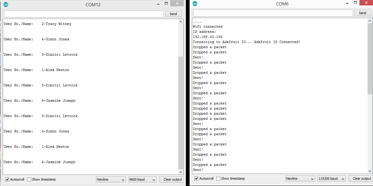
When few or many cards are scanned, the data get uploaded to adafruit io feeds. You can simply log in and check the details.


So this is all about IoT Based RFID Attendance System Using Arduino ESP8266 & Adafruit.io. For details tutorials and explanation you can check the video below.
Video Tutorial & Explanation

 & Live Dashboard")


15 Comments
esp8266 library is showing error
Does 13.56 mHz RFC card is must or. Should I use another frequency card?
This project really work or not
Rfid card is not working… Please help me ☹️
I did the project and it worked perfectly, but i need the names to show on io.adafruit.com instead of numbers, how do i do it? thanks. emmanuel francis
check ur connections, power must be 3.3V
How can you power this project without using the computer? What circuit configurations with which battery packs, etc?
Use any 5v dc adapter like mobile charger or battery pack.
How can I know the identification (UID) of the RFID card to load it in the code?
Sir suppose I am doing this project, do I have to do multiple modifications on the code. if it is like that then at which positions I have to modify.
thank you and will wait for your response.
Salvation! I need help. I tried the project but my esp card can’t connect to adafruit
I got an error saying that ‘WiFiClient’ does not name a type. How did you correct this?
Thanks for sharing this project. I have a question for you, why can’t you do that just using the ESP8266?
I am facing similar issue, do you know how to solve this?
There was an error when connecting to wifi. it keeps connecting and error shown up at the end.
Do you know how to solve this?
Traceback (most recent call last):
File “/Users/patricktan/Library/Arduino15/packages/esp8266/hardware/esp8266/3.0.2/tools/upload.py”, line 66, in
esptool.main(cmdline)
File “/Users/patricktan/Library/Arduino15/packages/esp8266/hardware/esp8266/3.0.2/tools/esptool/esptool.py”, line 3552, in main
esp.connect(args.before, args.connect_attempts)
File “/Users/patricktan/Library/Arduino15/packages/esp8266/hardware/esp8266/3.0.2/tools/esptool/esptool.py”, line 529, in connect
raise FatalError(‘Failed to connect to %s: %s’ % (self.CHIP_NAME, last_error))
esptool.FatalError: Failed to connect to ESP8266: Timed out waiting for packet header
Failed uploading: uploading error: exit status 1