

We will interface MPU6050 Gyro/Accelerometer Sensor with NodeMCU ESP8266 & measure tilt angle. The measured till angle is monitored on Blynk using IoT Cloud.
Overview
In this post we will learn how to Measure Tilt Angle using MPU6050 & NodeMCU ESP8266. This can be done by simply interfacing MPU6050 6 axis Gyro/Accelerometer Sensor with ESP8266. The Accelerometer sends X, Y, and Z acceleration forces. We need to convert the forces into X, Y, Z 3D angle to determine the 3D Orientation of the sensor. The measured tilt angle is sent to the Blynk Application using the Blynk cloud. Hence the tilting position can be monitored over IoT.
The gyroscope measures rotational velocity or rate of change of the angular position over time, along the X, Y and Z-axis. It uses MEMS technology and the Coriolis Effect for measuring. The outputs of the gyroscope are in degrees per second, so in order to get the angular position, we just need to integrate the angular velocity.
You can refer to the previous post where we measured tilt angle using MPU6050 Gyro/Accelerometer & Arduino: Measure Tilt Angle Using MPU6050. Apart from this the MPU6050 can also be used to measure and control speed of DC Motor.
Components Required
Following are the components required for making this project. All the components can be easily purchased from Amazon. The component purchased link is added.
| S.N. | Components | Quantity | Purchase Links |
|---|---|---|---|
| 1 | Nodemcu ESP8266 Board | 1 | Amazon | AliExpress |
| 2 | MPU6050 | 1 | Amazon | AliExpress |
| 3 | OLED Display | 1 | Amazon | AliExpress |
| 4 | Connecting Wires | 10 | Amazon | AliExpress |
| 5 | Breadboard | 1 | Amazon | AliExpress |
MPU6050 Gyro/Accelerometer Sensor
Introduction:

The InvenSense MPU-6050 sensor contains a MEMS accelerometer and a MEMS gyro in a single chip. It is very accurate, as it contains 16-bits analog to digital conversion hardware for each channel. Therefor it captures the x, y, and z channel at the same time. The sensor uses the I2C-bus to interface with the Arduino.
The MPU-6050 is not expensive, especially given the fact that it combines both an accelerometer and a gyro.
MPU6050 Pinout:
The MPU-6050 module has 8 pins:
INT: Interrupt digital output pin.
AD0: I2C Slave Address LSB pin. This is 0th bit in 7-bit slave address of device. If connected to VCC then it is read as logic one and slave address changes.
XCL: Auxiliary Serial Clock pin. This pin is used to connect other I2C interface enabled sensors SCL pin to MPU-6050.
XDA: Auxiliary Serial Data pin. This pin is used to connect other I2C interface enabled sensors SDA pin to MPU-6050.
SCL: Serial Clock pin. Connect this pin to microcontrollers SCL pin.
SDA: Serial Data pin. Connect this pin to microcontrollers SDA pin.
GND: Ground pin. Connect this pin to ground connection.
VCC: Power supply pin. Connect this pin to +5V DC supply.
3-Axis Gyroscope:
The MPU6050 consist of 3-axis Gyroscope with Micro Electro Mechanical System(MEMS) technology. It is used to detect rotational velocity along the X, Y, Z axes as shown in below figure.

3-Axis Accelerometer:
The MPU6050 consist 3-axis Accelerometer with Micro Electro Mechanical (MEMs) technology. It used to detect angle of tilt or inclination along the X, Y and Z axes as shown in below figure.

Circuit: ESP8266 & MPU6050 Tilt Angle Monitor on IoT Blynk
Here is the circuit diagram for interfacing MPU6050 Gyro/Accelerometer with NodeMCU ESP8266. The circuit can be assembled on breadboard.

Both the MPU6050 & OLED display are I2C Module. So we need only 2 wires for interfacing them with NodeCMU. The SDA pins of both modules are connected to D2 of NodeMCU ESP8266 & SCL to D1. Supply 3.3V power to both modules.

Setting Up Blynk IoT Application for Remote Weight Monitoring
Blynk is an application that runs over Android and IOS devices to control any IoT based application using Smartphones. It allows you to create your Graphical user interface for IoT application. Here we will set up the Blynk application to monitor MPU6050 Angles over Wi-Fi using NodeMCU ESP8266.
So download and install the Blynk Application from Google Play store. IOS users can download from the App Store. Once the installation is completed, open the app & sign-up using your Email id and Password.

Now follow the photos below to set up the complete Blynk application.

So create gauge and value display. After the successful creation of the Project, go back to setting and click on Send Email. You will get an Authenticate ID on registered mail. Save the Authenticate ID. You will need to enter this on code.
Source Code/Program
The source code/program for interfacing MPU6050 with ESP8266 on IoT cloud is given below. We will need few libraries to compile the code. So download the libraries from the link below and add it to Arduino Library.
- Adafruit_SSD1306 : https://github.com/adafruit/Adafruit_SSD1306
- Adafruit_GFX : https://github.com/adafruit/Adafruit-GFX-Library
- Blynk ESP8266 Library
Make sure to do the following changes in the code. Change the wifi SSDI & Password. And change the Blynk Authentication Token as well.

|
1 2 3 4 5 6 7 8 9 10 11 12 13 14 15 16 17 18 19 20 21 22 23 24 25 26 27 28 29 30 31 32 33 34 35 36 37 38 39 40 41 42 43 44 45 46 47 48 49 50 51 52 53 54 55 56 57 58 59 60 61 62 63 64 65 66 67 68 69 70 71 72 73 74 75 76 77 78 79 80 81 82 83 84 85 86 87 88 89 90 91 92 93 94 95 96 97 98 99 100 101 102 103 104 105 |
#include<Wire.h> #include <SPI.h> #define BLYNK_PRINT Serial #include <Blynk.h> #include <ESP8266WiFi.h> #include <BlynkSimpleEsp8266.h> #include <Adafruit_GFX.h> #include <Adafruit_SSD1306.h> #define SCREEN_WIDTH 128 // OLED display width, in pixels #define SCREEN_HEIGHT 64 // OLED display height, in pixels #define OLED_RESET -1 // Reset pin # (or -1 if sharing reset pin) Adafruit_SSD1306 display(SCREEN_WIDTH, SCREEN_HEIGHT, &Wire, OLED_RESET); char auth[] = "vB00BQor2wyZ927WnWe5JoBPgOi-fMQ7"; // You should get Auth Token in the Blynk App. char ssid[] = "Sri Krishna 3rd."; // Your WiFi credentials. char pass[] = "subbu@123"; const int MPU_addr=0x68; int16_t AcX,AcY,AcZ,Tmp,GyX,GyY,GyZ; int minVal=265; int maxVal=402; double x; double y; double z; void setup(){ Wire.begin(); Wire.beginTransmission(MPU_addr); Wire.write(0x6B); Wire.write(0); Wire.endTransmission(true); Serial.begin(9600); Blynk.begin(auth, ssid, pass); if(!display.begin(SSD1306_SWITCHCAPVCC, 0x3C)) { Serial.println(F("SSD1306 allocation failed")); for(;;); // Don't proceed, loop forever } display.display(); delay(2); display.clearDisplay(); display.clearDisplay(); display.setTextColor(WHITE); display.setTextSize(2); display.setCursor(0,5); display.print("MPU Angles"); display.display(); delay(3000); } void loop(){ Blynk.run(); Wire.beginTransmission(MPU_addr); Wire.write(0x3B); Wire.endTransmission(false); Wire.requestFrom(MPU_addr,14,true); AcX=Wire.read()<<8|Wire.read(); AcY=Wire.read()<<8|Wire.read(); AcZ=Wire.read()<<8|Wire.read(); int xAng = map(AcX,minVal,maxVal,-90,90); int yAng = map(AcY,minVal,maxVal,-90,90); int zAng = map(AcZ,minVal,maxVal,-90,90); x= RAD_TO_DEG * (atan2(-yAng, -zAng)+PI); y= RAD_TO_DEG * (atan2(-xAng, -zAng)+PI); z= RAD_TO_DEG * (atan2(-yAng, -xAng)+PI); Serial.print("AngleX= "); Serial.println(x); Serial.print("AngleY= "); Serial.println(y); Serial.print("AngleZ= "); Serial.println(z); Serial.println("-----------------------------------------"); display.clearDisplay(); display.setTextSize(2); display.setCursor(0,0); display.print("X: "); display.println(x); display.setTextSize(2); display.setCursor(0,20); display.print("Y: "); display.println(y); display.setTextSize(2); display.setCursor(0,40); display.print("Z: "); display.println(z); display.display(); Blynk.virtualWrite(V2, x); Blynk.virtualWrite(V3, y); Blynk.virtualWrite(V4, z); delay(1000); } |
Output/Results
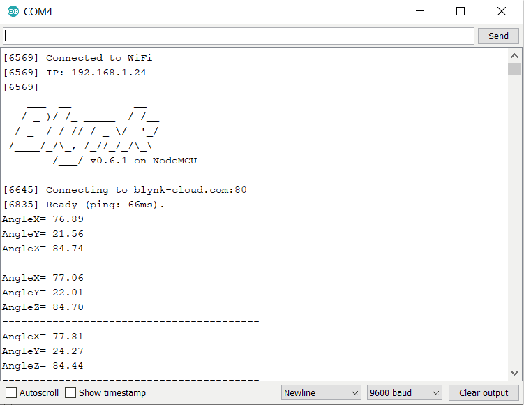
So once the code is uploaded, you can click on serial monitor to check the outputs. You need to tilt the MPU6050 Gyro/Accelerometer to detect the angular position of X, Y & Z axis. The same tilting angles can be observed on OLED Display as well.


Since MPU6050 ESP8266 is connected to the internet, the ESP8266 will start sending the data to Blynk Application. You can open your serial monitor and check the status as shown below.
Now you can simply see the status on Blynk App as well. The Blynk will start displaying the gauge with changing parameters of X, Y & Z angles.

 & Live Dashboard")


3 Comments
where is the source code to download?
Hello, how are you? I wonder if you used any library for the MPU6050. Library usually is needed to define its x, y and z axes.
is there a way to set 0 deg in this code or in the sensor?