

Overview: IoT ESP32 Based PM2.5 Monitoring with Air Freshener System
In this IoT project, we will design an IoT ESP32 & PMS5003 Based PM2.5 & PM10 Monitoring System along with an Automatic Air Freshener System. The device can monitor and measure the PM2.5 & PM10 concentration in the air. It can also activate the air freshener when the PM Level exceeds the danger value. The device can be used in the house, industry, schools, office, and around crowded places.
Particulate Matter (PM) refers to microscopic particles of solid or liquid matter suspended in the air. PM is particulate matter, and 10 and 2.5 are diameter measurements: 10 micrometers or less, and 2.5 micrometers or less. Particulates are the most harmful form of air pollution. PM2.5 & PM10 has the ability to penetrate deep into the lungs, blood streams, and brain, causing health problems including heart attacks, respiratory disease, and premature death.
So, we have proposed an IoT Based System using ESP32 WiFi Module & PMS5003 Particulate Matter PM2.5 & PM10 Sensor. The device can be embedded on a small PCB. The device when powered on starts measuring the Particulate Matter Concentration in Air & displays the real-time value on a 0.96″ OLED Display. The ESP32 also connects to the WiFi Network and uploads the data to the Web Server. Using the Local IP address of ESP32, you can get the PM1.0, PM2.5 & PM10 value on any Web Browser. The Web Page doesn’t need any refreshing as the Ajax code is already implemented.
The Air Quality Index (AQI) value anything above 50 is unhealthy for breathing. So, when the pollution level exceeds in air, the fan turns on automatically to blow fresh air. Instead of Fan, you can use any other air freshening device like a humidifier connected to the relay.
Bill of Materials
The Bill of Materials or the list of components required for making this system is given below. You can purchase all the components online from Amazon. The table contains the purchase link of all the components.
| S.N. | Components Name | Quantity | Purchase Links |
|---|---|---|---|
| 1 | ESP32 WiFi Module | 1 | Amazon | AliExpress |
| 2 | PMS5003 PM2.5 Sensor | 1 | Amazon | AliExpress |
| 3 | 12V DC Fan | 1 | Amazon | AliExpress |
| 4 | 0.96" I2C OLED Display | 1 | Amazon | AliExpress |
| 5 | 5V Relay | 1 | Amazon | AliExpress |
| 6 | 7806 6V Voltage Regulator | 1 | Amazon | AliExpress |
| 7 | 1N4007 Diode | 1 | Amazon | AliExpress |
| 8 | Resistor 330-ohm | 1 | Amazon | AliExpress |
| 9 | Buzzer 5V | 1 | Amazon | AliExpress |
| 10 | Transistor BC547 | 1 | Amazon | AliExpress |
| 11 | DC Power Jack | 1 | Amazon | AliExpress |
| 12 | 12V DC Power Supply | 1 | Amazon | AliExpress |
| 13 | Female Headers | Multiple | Amazon | AliExpress |
| 14 | Connecting Wires | Multiple | Amazon | AliExpress |
PMS5003 PM2.5/PM10 Sensor Module
PMS5003 is a kind of digital and universal particle concentration sensor, which can be used to obtain the number of suspended particles in the air. It output PM Concentration in the form of a digital interface.

The laser scattering principle is used for PMS5003. This means it produces scattering by using a laser to radiate suspending particles in the air, then collect scattering light to a certain degree, and finally obtain the curve of scattering light change with time.
The sensor has a UART interface you can use a USB-Serial converter and parse the data on a computer. The sensor operates between 4.5V to 5V with an active current consumption of 100mA. The sensor measures PM1.0, PM2.5 & PM10 from an effective range of 0~500 μ g/m³ & with a maximum range of 1000 μ g/m³. You can check the PMS5003 Datasheet if you want to learn more about this sensor.
PMS5003 Specifications
- Range of measurement: 0.3~1.0;1.0~2.5;2.5~10 μ m
- Effective Range: 0~500 μ g/m³
- Maximum Range: ≥1000 μ g/m³
- Resolution: 1 μ g/m³
- DC Power Supply: Typ:5.0 / Min:4.5 / Max: 5.5V
- Active Current: ≤100 mA
- Standby Current: ≤200 μ A
- Working Temperature Range: -10~+60 ℃
- Working Humidity Range: 0~99%
- Sensor Module Dimensions: 50 × 38 × 21mm
PMS5003 Pinout
The PMS5003 has 8 pins out of which only 4 pins are usable. The pin 1 is from right side and requires 8-pin connector (1.25mm raster).
| Pin | Function | Description | Remarks |
|---|---|---|---|
| 1 | VCC | Supply voltage 5V | 4.5 – 5.5V |
| 2 | GND | Ground | |
| 3 | SET | HIGH or SUSPENDED – work mode LOW – sleep mode |
3.3V logic |
| 4 | RXD | UART/TTL data recieve | 3.3V logic |
| 5 | TXD | UART/TTL data transmit | 3.3V logic |
| 6 | Reset | LOW to reset | 3.3V logic |
| 7 | NC | Not connected | |
| 8 | NC | Not connected |
Circuit Design & Hardware
Now, let us design the complete system. The main components of the system are ESP32, PMS5003 & OLED Display along with Relay, Buzzer, DC Fan and Power Supply Unit. We use 12V/9V to power on the entire circuit. The 12V power supply is converted into 5V using 7805 voltage regulator IC. The ESP32 & PMS5003 is then powered by 5V. The Relay also requires 5V but the DC Fan requires 12V for activation. Incase if you want to use humidifier, you need to change the relay connection and relay type.
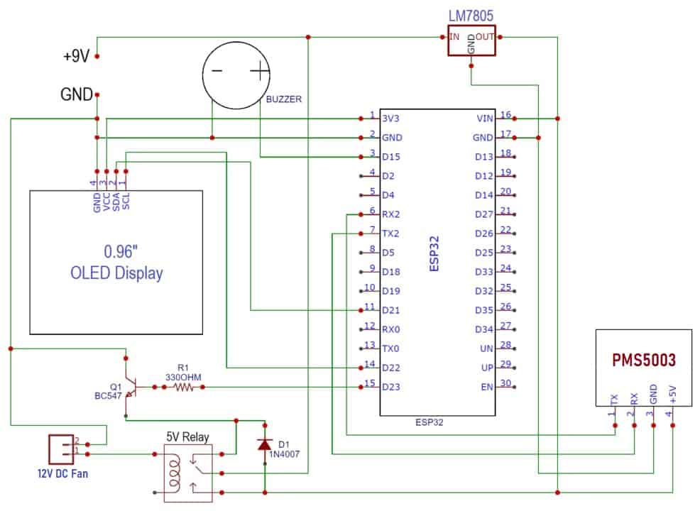
The OLED Display is an I2C module, hence it is connected to ESP32 I2C pins, i.e SDA & SCL pins are connected to ESP32 GPIO21 & GPIO22 respectively. The relay is switched ON via BC547 NPN Transistor which is connected to GPIO23 of ESP32. Similarly, the PMS5003 sensor is connected to the UART2 pin of ESP32, i.e. TX & RX of PMS5003 is connected to RX2 & TX2 of ESP32. The 5V buzzer is connected to GPIO15 of ESP32, which only gets activated if the PM2.5 level crosses the threshold value defined in the code.
PCB Designing & Gerber File: IoT ESP32 Based PM2.5 Monitoring with Air Freshener System
The PCB for IoT ESP32 Based PM2.5 Monitoring with Air Freshener System has been designed in EasyEDA online PCB making tool. Below is the front view and Back View of the PCB.

The Gerber File for the PCB is given below. You can simply download the Gerber File and order the PCB from ALLPCB at 1$ only.
PCB Ordering, Soldering & Mounting
You can use this Gerber file to order high quality PCB for this project. To do that visit the ALLPCB official website by clicking here: https://www.allpcb.com/.

You can now upload the Gerber File by choosing the Quote Now option. From these options, you can choose the Material Type, Dimensions, Quantity, Thickness, Solder Mask Color and other required parameters.

After filling all details, select your country and shipping method. Finally you can place the order.
So after a week I got the PCB from ALLPCB. The PCB quality is good and excellent.

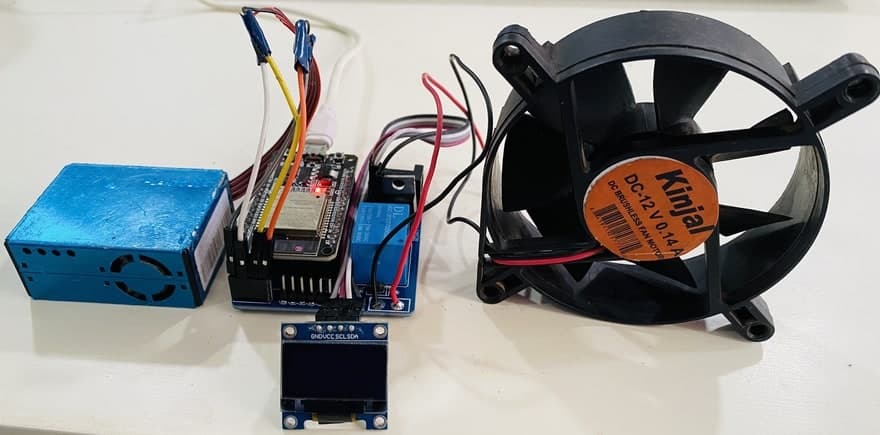
Finally after soldering and mounting all the components on the received PCB, the board looks great. You can make this hardware more beautiful by designing a 3D casing to properly place and pack the parts.
Source Code/Program
Now let us see the code for the project: IoT ESP32 Based PM2.5 Monitoring with Air Freshener System. The code requires few libraries for compilation. You can download the required libraries from the following link below.
- PMS5003 Library: https://github.com/fu-hsi/PMS
- Adafruit GFX Library: https://github.com/adafruit/Adafruit-GFX-Library
- SSD1306 Library: https://github.com/adafruit/Adafruit_SSD1306
|
1 2 |
const char* ssid = "Alexahome"; const char* password = "loranthus"; |
From the line above, change the WiFi SSID & Password.
|
1 |
if (val2.toFloat() >= 150) |
Change the threshold value to the desired value. Currently, it is set to 150. This threshold value is used to turn ON/OFF the Relay as well as the Buzzer.
The complete code of the project is given below. You can select the ESP32 Board from the Board Manager list and upload the code to the ESP32 Board.
|
1 2 3 4 5 6 7 8 9 10 11 12 13 14 15 16 17 18 19 20 21 22 23 24 25 26 27 28 29 30 31 32 33 34 35 36 37 38 39 40 41 42 43 44 45 46 47 48 49 50 51 52 53 54 55 56 57 58 59 60 61 62 63 64 65 66 67 68 69 70 71 72 73 74 75 76 77 78 79 80 81 82 83 84 85 86 87 88 89 90 91 92 93 94 95 96 97 98 99 100 101 102 103 104 105 106 107 108 109 110 111 112 113 114 115 116 117 118 119 120 121 122 123 124 125 126 127 128 129 130 131 132 133 134 135 136 137 138 139 140 141 142 143 144 145 146 147 148 149 150 151 152 153 154 155 156 157 158 159 160 161 162 163 164 165 166 167 168 169 170 171 172 173 174 175 176 177 178 179 180 181 182 183 184 185 186 187 188 189 190 191 192 193 194 195 196 197 |
#include <WiFi.h> #include <WebServer.h> #include "PMS.h" #include <HardwareSerial.h> #include <Wire.h> #include <Adafruit_GFX.h> #include <Adafruit_SSD1306.h> PMS pms(Serial2); PMS::DATA data; #define SCREEN_WIDTH 128 // OLED display width, in pixels #define SCREEN_HEIGHT 64 // OLED display height, in pixels #define OLED_RESET -1 // Reset pin # (or -1 if sharing reset pin) Adafruit_SSD1306 display(SCREEN_WIDTH, SCREEN_HEIGHT, &Wire, OLED_RESET); String val1; String val2; String val3; int relayPin = 23; int buzzerPin = 15; const char* ssid = "Alexahome"; const char* password = "loranthus"; WebServer server(80); void setup() { Serial.begin(9600); Serial2.begin(9600); pinMode(relayPin, OUTPUT); pinMode(buzzerPin, OUTPUT); digitalWrite(relayPin, LOW); digitalWrite(buzzerPin, LOW); if (!display.begin(SSD1306_SWITCHCAPVCC, 0x3C)) { Serial.println(F("SSD1306 allocation failed")); for (;;); // Don't proceed, loop forever } display.display(); delay(100); display.clearDisplay(); display.clearDisplay(); display.setTextColor(WHITE); display.setTextSize(1); display.setCursor(10, 20); display.print("Initializing...."); display.display(); delay(3000); Serial.println("Connecting to "); Serial.println(ssid); //connect to your local wi-fi network WiFi.begin(ssid, password); //check wi-fi is connected to wi-fi network while (WiFi.status() != WL_CONNECTED) { delay(500); Serial.print("."); } Serial.println(""); Serial.println("WiFi connected..!"); Serial.print("Got IP: "); Serial.println(WiFi.localIP()); display.clearDisplay(); display.setTextColor(WHITE); display.setTextSize(1); display.setCursor(20, 20); display.print("WiFi connected..!"); display.setTextSize(1); display.setCursor(20, 40); display.print(WiFi.localIP()); display.display(); delay(4000); server.on("/", handle_OnConnect); server.onNotFound(handle_NotFound); server.begin(); Serial.println("HTTP server started"); delay(2000); } void loop() { if (pms.read(data)) { val1 = data.PM_AE_UG_1_0; val2 = data.PM_AE_UG_2_5; val3 = data.PM_AE_UG_10_0; Serial.println("Air Quality Monitor"); Serial.println("PM1.0 :" + val1 + "(ug/m3)"); Serial.println("PM2.5 :" + val2 + "(ug/m3)"); Serial.println("PM10 :" + val3 + "(ug/m3)"); Serial.println(""); display.clearDisplay(); display.setTextSize(1); display.setCursor(10, 10); display.print("PM1.0: "); display.print(val1); display.print(" ug/m3"); display.setCursor(10, 30); display.print("PM2.5: "); display.print(val2); display.print(" ug/m3"); display.setCursor(10, 50); display.print("PM10 : "); display.print(val3); display.print(" ug/m3"); display.display(); delay(2000); } if (val2.toFloat() >= 150) { digitalWrite(relayPin, HIGH); digitalWrite(buzzerPin, HIGH); } else { digitalWrite(relayPin, LOW); digitalWrite(buzzerPin, LOW); } server.handleClient(); } void handle_OnConnect() { server.send(200, "text/html", SendHTML(val1.toFloat(), val2.toFloat(), val3.toFloat())); } void handle_NotFound() { server.send(404, "text/plain", "Not found"); } String SendHTML(int val1, int val2, int val3) { String ptr = "<!DOCTYPE html> <html>\n"; ptr += "<head><meta name=\"viewport\" content=\"width=device-width, initial-scale=1.0, user-scalable=no\">\n"; ptr += "<title>Wireless Weather Station</title>\n"; ptr += "<style>html { font-family: Helvetica; display: inline-block; margin: 0px auto; text-align: center;}\n"; ptr += "body{margin-top: 50px;} h1 {color: #444444;margin: 50px auto 30px;}\n"; ptr += "p {font-size: 24px;color: #444444;margin-bottom: 10px;}\n"; ptr += "</style>\n"; ptr += "<script>\n"; ptr += "setInterval(loadDoc,1000);\n"; ptr += "function loadDoc() {\n"; ptr += "var xhttp = new XMLHttpRequest();\n"; ptr += "xhttp.onreadystatechange = function() {\n"; ptr += "if (this.readyState == 4 && this.status == 200) {\n"; ptr += "document.body.innerHTML =this.responseText}\n"; ptr += "};\n"; ptr += "xhttp.open(\"GET\", \"/\", true);\n"; ptr += "xhttp.send();\n"; ptr += "}\n"; ptr += "</script>\n"; ptr += "</head>\n"; ptr += "<body>\n"; ptr += "<div id=\"webpage\">\n"; ptr += "<h1>Particulate Matter Monitoring</h1>\n"; ptr += "<p>PM1.0: "; ptr += val1; ptr += " ug/m3</p>"; ptr += "<p>PM2.5: "; ptr += val2; ptr += " ug/m3</p>"; ptr += "<p>PM10: "; ptr += val3; ptr += " ug/m3</p>"; ptr += "</div>\n"; ptr += "</body>\n"; ptr += "</html>\n"; return ptr; } |
Device Testing & Operations
After succesfully uploading the code, the device becomes ready for the operation. The OLED disply will says sensor initializing. The PMS5003 sensor requires some time to get heated. Once, it get heated the fan inside it starts rotating, the correct value of PM1.0, PM2.5 & PM10 will be displayed on OLED Screen.

To test the working of the sensor, bring some materials that produce smoke or some gases. The smoke can be introduced near the sensor fan. In my case, I preferred an incense stick to test the device. As soon as the smoke is introduced near the sensor, the PM1.0, PM2.5 & PM10 value increased & can be observed on OLED Screen. Also, the fan will turn on and starts blowing air in order to keep the air fresh.

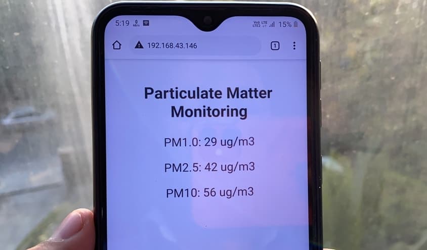
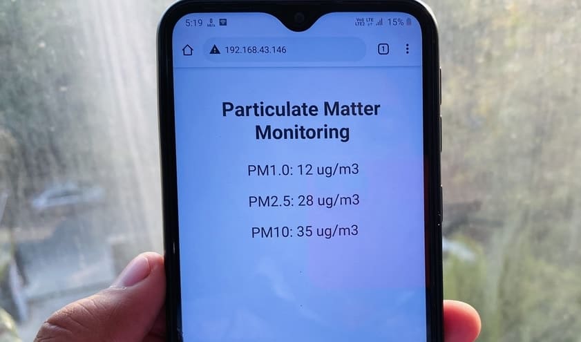
You can also monitor the PM1.0, PM2.5, PM10 on the IoT platform wirelessly. To do that we have added a web server code to the above program. Using the webserver code the Particulate Matter Data can be monitored on ESP32 Webserver. To access the webserver, press the reset button on the OLED screen. It will display the IP Address.

You can now use the IP Address and paste it in your web browser of computer or mobile phone. After hitting enter, a page will be displayed where you can see the PM1.0, PM2.5, PM10 data. You don’t need to refresh the page, again and again, to see the data as data is updated automatically after few seconds. This is because The code already has the AJAX (Asynchronous Javascript And Xml) script so that we can request data from the server asynchronously (in the background) without refreshing the page.
Video Tutorial & Demo

 & Live Dashboard")


4 Comments
Could it be your BC547 has collector and emitter switched?
I am rather baffled by the way you switch your relay. one of the coil ends is not connected to anything, the diode should be over the coil, not over the switch contacts.
it seems like you mixed up the coil with the contacts but even then it is very puzzling
Would you sell working built up units?
7806 should be 7805, right?